Magnetic flowing deformation elastomer frequency shift type attenuator and control method

A magnetorheological elastomer and vibration absorber technology, which is applied in vibration suppression adjustment, non-rotational vibration suppression, etc., can solve the problems of narrow control frequency band, insignificant influence of vibration absorber characteristics, and high energy consumption, etc., to achieve vibration reduction frequency Wide bandwidth, easy control method, and high system reliability

Inactive Publication Date: 2007-04-18
UNIV OF SCI & TECH OF CHINA
View PDF2 Cites 42 Cited by
  • Summary
  • Abstract
  • Description
  • Claims
  • Application Information

AI Technical Summary

Problems solved by technology

However, the traditional passive vibration absorber has many shortcomings, such as the control frequency band is very narrow and cannot be adjusted, so it can only reduce the vibration of a steady-state vibration with a fixed excitation frequency. When the excitation frequency deviates a little, the vibration reduction effect will be sharp deteriorating, or even worse
And increasing the bandwidth will make it unwieldy etc.
[0004] The vibration absorbing device mentioned in the invention patent of application number 96107066.8 is designed using the principle of a passive vibration absorber. Due to the narrow bandwidth of vibration reduction, it can only be solved by increasing the damping or the weight of the shock absorber and using multiple vibration reduction weights. , but increasing the damping will reduce the vibration damping effect, and increasing the mass and number of vibration damping weights will make the shock absorber bulky. In addition, this method has a very limited increase in the vibration damping bandwidth, generally only a few hertz
In addition, the invention patent with application number 02131043.2 mentions an active magneto-rheological fluid damping vibration absorber and its installation method, which can use linear motors, metal springs and magnetorheological fluid dampers to actively change parameters such as system control force and damping To achieve the purpose of "best tuning", but this control method is complicated, because it needs to drive the linear motor, it will consume more energy, and according to the principle of the vibration absorber, changing these parameters has no significant impact on the characteristics of the vibration absorber

Method used


Image

  • Magnetic flowing deformation elastomer frequency shift type attenuator and control method
  • Magnetic flowing deformation elastomer frequency shift type attenuator and control method
  • Magnetic flowing deformation elastomer frequency shift type attenuator and control method

Examples


Embodiment 1

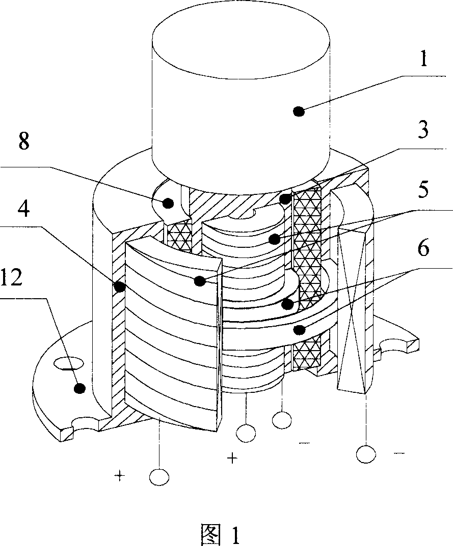
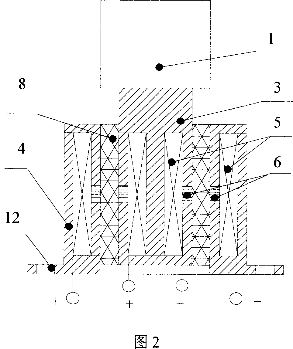
[0029] Embodiment 1: The shear-type magnetorheological elastomer frequency-shifting vibration absorber shown in Figure 1 and Figure 2 is composed of an inner sleeve 3 and an outer sleeve 4, a coil 5, a magnetic isolation ring 6, a magnetorheological Elastomer 8 and vibration-absorbing mass 1, base 12 constitute, sleeve and base are made of electrical pure iron, magnetic isolation ring is made of brass, and vibration-absorbing mass is also made of brass. The outer sleeve 4 is cylindrical, and the cross-sectional shape of its half is C-shaped, and the C-shaped opening faces inward, that is, there is a cavity inside the sleeve and an opening on the inner side wall. The coil 5 is just placed in the cavity, and the C-shaped opening on the inner side wall The opening is closed with an annular magnetic isolation ring 6, and the inner sleeve 3 is columnar or cylindrical (that is, there may be a longitudinal through hole or no longitudinal through hole at its axis), and the cross-sectio...

Embodiment 2

[0036] Embodiment 2: The tension-compression type magnetorheological elastomer frequency-shifting vibration absorber shown in Figure 4 consists of a U-shaped iron core 2, a magnetorheological elastomer 8, an armature 9, a vibration-absorbing mass 1, a base 12 and The coil 5 is formed, wherein the U-shaped iron core 2 and the armature 9 are made of industrial pure iron, the coil 5 is wound around the bottom of the U-shaped iron core, and the armature 9 is horizontally placed on the upper part, and the armature is strip-shaped. A sheet magnetorheological elastomer 8 is fixed between the armature 9 and the U-shaped iron core 2, and the vibration-absorbing mass 1 is fixed on the armature 9 with threads. The screw holes on the base 12 are fixed to the damping object, and other control methods are the same as in the first embodiment. It works in the state of tension and compression, which can eliminate the linear vibration consistent with the vibration direction of the vibration dam...

Embodiment 3

[0037] Embodiment 3: The torsion-bending composite magnetorheological elastomer frequency-shifting vibration absorber as shown in Figure 5 consists of an upper plate 10, a lower plate 11, a coil 5, a columnar iron core 7, a magnetorheological elastomer 8, and a base The seat 12 and the vibration-absorbing mass 1 are formed, the upper plate 10, the lower plate 11 and the columnar iron core 7 are made of industrial pure iron, the base 12 is made of aluminum, the columnar iron core 7 is wound around the coil 5, and the columnar iron core 7 is up and down. Fix one end of the upper plate 10 and the lower plate 11 or any part in the middle with threads, and the remaining parts between the two plates are fixed with a block-shaped magnetorheological elastomer 8, the upper plate 10, the lower plate 11, the magnetorheological The elastic body 8 forms a sandwich biscuit-like sandwich beam as a whole and welds one end of it to the base to form a cantilever beam. The other end of the cantil...


PUM


Abstract

The inventive vibration absorber comprises an execution unit, a control unit and a sensor. The execution unit consists of a magnetic inductor, a coil, a magnetic rheological elastic body, a vibration-absorbing mass block and a base. The above magnetic inductor consists of inner and outer sleeves, or a U-shaped iron-core and an armature or top and bottom plates and a column iron-core. Between inner and outer sleeves, the U-shaped iron-core and the armature or the top and bottom plates are filled the magnetic rheological elastic bodies. By regulating the voltage on the coil, the rigidity and the elasticity of the magnetic rheological elastic body are regulated to make its vibration frequency change, so as to make the vibration frequency of the vibration absorber execution unit is the same as that of the vibration-damping object.

Description

(1) Technical field: [0001] The invention relates to a vibration damping device and a control method applied to machinery and electrical equipment. (two) background technology: [0002] In the past mechanical and electrical equipment, due to the lack of an effective shock absorption system, the mechanical and electrical equipment were damaged prematurely or caused noise pollution to the environment. [0003] Existing vibration control methods can be divided into active control, passive control, and semi-active control. Passive control has no adjustment ability at all, has its limitations, and is only suitable for narrow-band vibration control. Active control is superior to passive control and can be actively adjusted, suitable for broadband vibration control. However, active control belongs to force control, which needs to directly provide the energy of control force, and the cost is high and the technology is relatively complicated. Semi-active control belongs to paramet...

Claims


Application Information

Patent Timeline
Patent Type & Authority Applications(China)
IPC IPC(8): F16F9/53
Inventor 邓华夏龚兴龙张先舟张培强
Owner UNIV OF SCI & TECH OF CHINA
Why Eureka
Try Eureka