Boiling bed residual oil hydrocracking process

A technology of hydrocracking and bed residue, which is applied in the fields of hydrocarbon oil cracking and petroleum industry, etc., which can solve the problems of not being able to give full play to the high dispersion and high activity of the catalyst, and achieve the effects of improving utilization rate, improving product quality and reducing wear

Active Publication Date: 2007-04-25
CHINA PETROLEUM & CHEM CORP +1
View PDF1 Cites 11 Cited by
  • Summary
  • Abstract
  • Description
  • Claims
  • Application Information

AI Technical Summary

Problems solved by technology

It can be seen from its description that the oil-soluble catalyst and the supported catalyst are mixed together in the reactor, and because the oil-soluble catalyst has a strong adsorption capacity, even when the catalyst addition is 1-60 μg / g, it will The oil-soluble catalyst is adsorbed on the supported catalyst to form a new supported catalyst, which cannot fully exert the high dispersion and high activity of the catalyst

Method used


Image

  • Boiling bed residual oil hydrocracking process

Examples


Embodiment approach

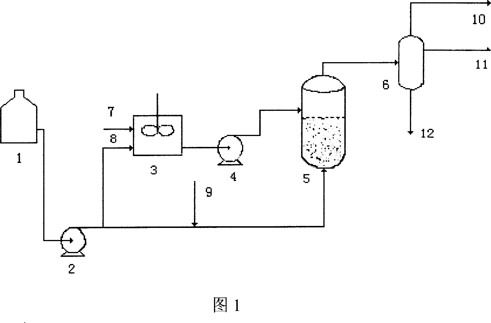
[0023] As shown in Figure 1, the process flow of the fluidized bed residual oil hydrogenation using supported and dispersed catalysts is as follows: all or part of the heavy and residual oil raw materials in the raw material tank 1 are pressurized by the pump and then mixed with high-pressure hydrogen 9 for further processing. The way of feed enters the ebullating bed reactor that load-type catalyst is housed from the bottom of ebullating bed reactor 5 to keep the catalyst boiling, and part of the raw material or other hydrocarbons and catalyst aqueous solution from the raw material tank 1 and the raw material pump 2 are mixed in the mixer 3 Mix well and evenly in the medium, and enter the liquid phase area without catalyst or the sedimentation area of ​​the loaded catalyst through the dispersed catalyst delivery pump 4 of the ebullated bed reactor. The supported catalyst is in contact with the dispersed water-soluble catalyst to carry out catalytic hydrogenation reaction, and ...

Embodiment 1-2

[0029] This example is an ebullating bed hydrogenation test using a supported catalyst and a dispersed catalyst. The specific operation process is shown in Figure 1. The residual oil raw material in the raw material tank 1 is pressurized by a pump and then mixed with high-pressure hydrogen 9. The above feed enters the ebullating bed reactor equipped with a supported catalyst from the bottom of the reactor 5 to keep the catalyst boiling. From the raw material tank 1 and Part of the raw materials of the raw material pump 2 and the catalyst aqueous solution are fully mixed in the multi-stage shear tank 3, and then enter the catalyst-free liquid phase area of ​​the ebullated bed reactor through the dispersed catalyst delivery pump 4. Under the specified reaction conditions, from the reactor The heavy residue raw material entering from the bottom contacts with the supported catalyst and the dispersed water-soluble catalyst successively to carry out catalytic hydrogenation reaction,...


PUM

PropertyMeasurementUnit
densityaaaaaaaaaa
diameteraaaaaaaaaa
specific surface areaaaaaaaaaaa

Abstract

The invention disclosed a kind of dreg oil hydrogenating technology on bubbling bed. The invention disperses the scattered water-soluble catalyst uniformly in the heavy dreg oil; the catalyst enters the bubbling bed reactor from the top part of the loading catalyst's bed; at the same time, the heavy dreg oil together with hydrogen enters the bubbling bed reactor from the below part of the reactor; hydrogenating the material under proper conditions; fractionating the reacted product to get gas, distillate and end oil. The scattered catalyst can reduce the amount of loading catalyst in the bubbling reactor so as to increase the liquid holdup of the reactor and increase its handling ability; the scattered catalyst has strong adsorbability, it can adsorb the smuggled fine catalyst powder from the rising air current and liquid. The fine powder settled on the loading catalyst bed so it's easier to separate the solid granules and the liquid.

Description

technical field [0001] The invention relates to a heavy and residue oil fluidized bed hydrocracking process. Background technique [0002] With the vigorous development of heavy crude oil and the changes in the demand structure of petroleum products worldwide, the market demand for light fuel oil continues to grow rapidly and the demand for heavy fuel oil decreases rapidly. The advanced processing technology of heavy and residual oil has become a The focus of refinery industry development. Fluidized bed residual oil hydrogenation technology is one of the important means for processing heavy and residual oil raw materials. Conventional ebullating bed residual oil hydrogenation technology usually uses a supported catalyst, which is kept in a boiling state by controlling the flow rate of gas and liquid. To make full use of the reaction space of the reactor, it is necessary to install as much catalyst as possible to improve the processing capacity of the device. The amount of ...

Claims


Application Information

Patent Timeline
Patent Type & Authority Applications(China)
IPC IPC(8): C10G47/02
Inventor 贾丽杨涛李鹤鸣贾永忠刘建锟葛海龙
Owner CHINA PETROLEUM & CHEM CORP
Why Eureka
Try Eureka