Mechanical self-excited interactive hydraulic pulse drill bit pup joint

An interactive and self-excited technology, applied to drill bits, vibration drilling, drilling equipment, etc., can solve the problems of complex structure and low reliability, and achieve the effect of good stability, high reliability and simple structure

Inactive Publication Date: 2007-04-25
SICHUAN UNIV
View PDF1 Cites 2 Cited by
  • Summary
  • Abstract
  • Description
  • Claims
  • Application Information

AI Technical Summary

Problems solved by technology

Since the drilling tool uses a hydraulic oscillator as the vibration source, and the hydraulic oscillator adopts the self-excitation mechanism design of the Himuhelz resonant cavity, under the impact of the high-speed jet, the structural size of each cavity c

Method used


Image

  • Mechanical self-excited interactive hydraulic pulse drill bit pup joint
  • Mechanical self-excited interactive hydraulic pulse drill bit pup joint

Examples


Embodiment Construction

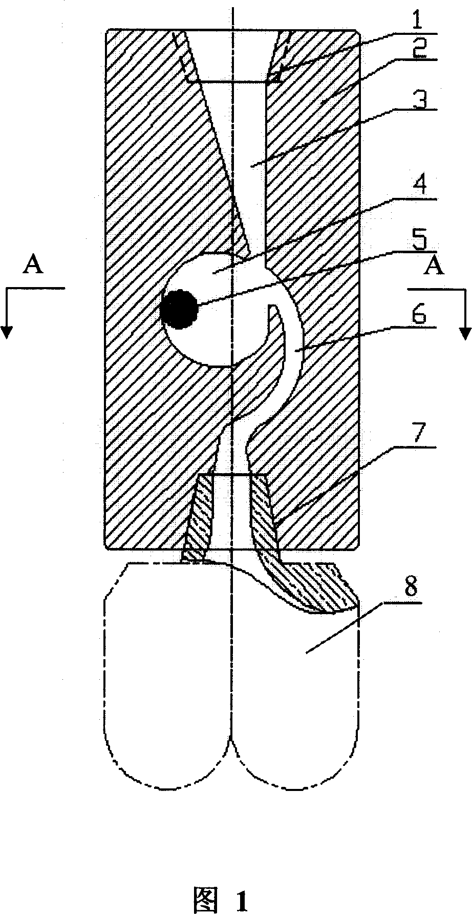
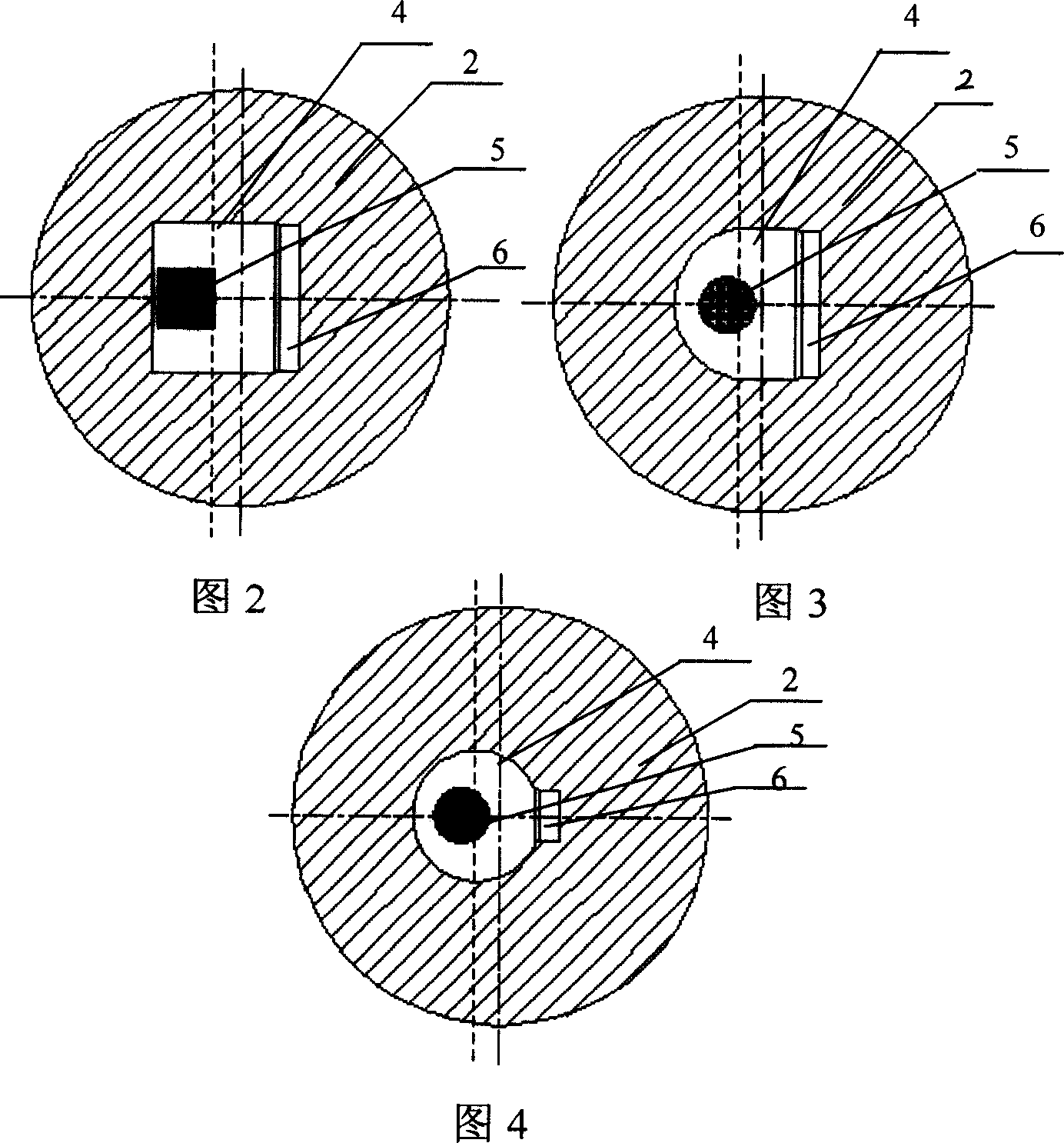
[0022] In this embodiment, the shape and structure of the sub-joint of the mechanical self-excited interactive hydraulic pulsation drill bit are shown in Figures 1 and 3, the sub-joint body 2 is an integral cylinder; the sub-joint body is provided with a mechanical self-excited pulsation cavity 4 , the mechanical self-excited pulsation chamber is placed with a spherical flow-around oscillating body 5, and the mechanical self-excited pulsation chamber is located in the middle of the pup joint body, and is a cavity formed by a combination of a hemisphere and a cylinder of equal diameter (as shown in Figure 3 ), the centerline of the cavity formed by the combination of the hemisphere and the equal-diameter cylinder is parallel to the centerline of the sub-section body 2 and moved to the left by a distance; The connecting screw hole I in the upper part communicates with the connecting screw hole II located at the lower part of the nipple body through the outlet flow channel 6. The ...


PUM


Abstract

The invention relates to a short section of mechanical interactive hydraulic ripple drill bit, comprising short section body. Mechanical interactive ripple cavity, in which flowing oscillating body is set, is set in the short section body. The mechanical interactive ripple cavity is connected with connecting screw hole I on the upper of short section body by the inlet channel and it is connected with connecting screw hole II on the lower of short section body. Connecting screw hole I is used to connect drill collar and connecting screw hole II is used to connect drill bit. Under the effect of high speed liquid flow oscillating body rotates in the mechanical interactive ripple cavity at a high speed and generates cyclical wallop so that flow oscillating body and mechanical interactive ripple cavity become vibration sources in working. Encouragements of the mechanical interactive ripple cavity and generated by mechanical interdiction from flow oscillating body have a common influence to form ripple liquid with high frequency, which is jetted from the nozzle connected with inner cavity of drill bit. The efficiency of rock breakage is improved largely.

Description

technical field [0001] The invention belongs to a drill bit sub-joint, in particular to a drill bit sub-joint used in petroleum and natural gas exploitation and other geological drilling. Background technique [0002] When the drill bit breaks rocks in deep formations, there is generally the problem of low rock breaking efficiency, which restricts the improvement of the drilling speed of drilling machines and makes the production cost high. Around the solution of this problem, people have carried out research on the improvement of the drill pup joint. The Chinese patent No. ZL200420041254.X discloses a jet-suction ball valve type pulse vibration drilling tool. It is composed of body and drill string connecting puppet, etc. The drill bit driving connecting puppet is assembled with the shell at the lower end of the shell, and the upper end and the lower end are respectively connected with the connecting sleeve and the drill bit. The middle part of the connecting sleeve is pro...

Claims


Application Information

Patent Timeline
IPC IPC(8): E21B7/24E21B10/60
CPCE21B7/18
Inventor 曹叔尤魏强刘兴年黄尔庄保堂孙健杨克君周晓泉
Owner SICHUAN UNIV
Why Eureka
Try Eureka