Adjustable light pulse time-delay device with wide bandwidth and multiple gains based on stimulated brillouin scatter

A technology of stimulated Brillouin and pulse delay, applied in optics, nonlinear optics, coupling of optical waveguides, etc., can solve the problem of slow light relative delay reduction and so on

Inactive Publication Date: 2007-05-09
HARBIN INST OF TECH
View PDF0 Cites 15 Cited by
  • Summary
  • Abstract
  • Description
  • Claims
  • Application Information

AI Technical Summary

Problems solved by technology

[0003] However, the Brillouin gain bandwidth in the optical fiber is narrow, generally only 30-50MHz, so the pulse light with a narrow pulse bandwidth (less than 15ns) will be significantly distorted when the pulse light is amplifie

Method used


Image

  • Adjustable light pulse time-delay device with wide bandwidth and multiple gains based on stimulated brillouin scatter

Examples


specific Embodiment approach 1

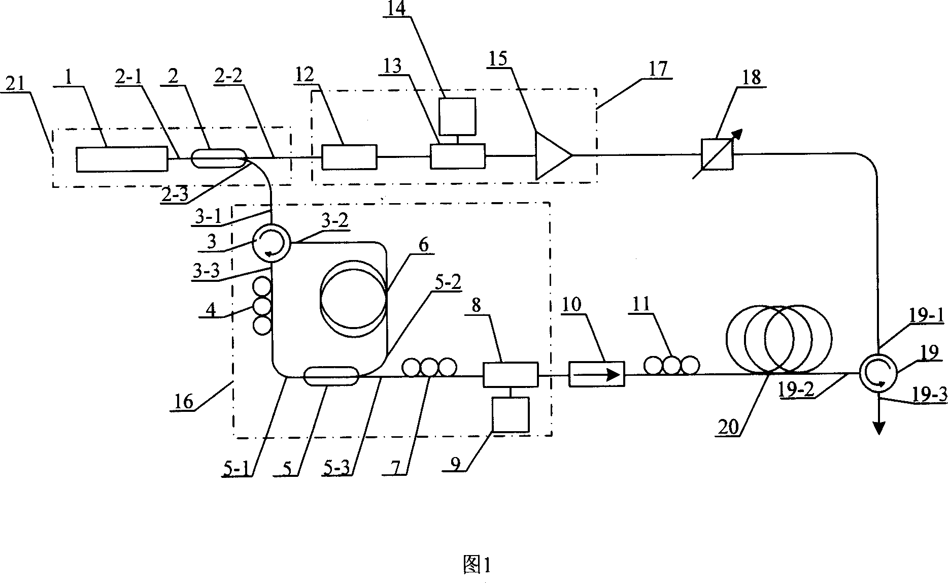
[0008] Specific embodiment one: illustrate this embodiment in conjunction with Fig. 1, this specific embodiment consists of laser source 21, pumping light source 17, detection pulse light source 16, fiber optic isolator 10, the 3rd polarization controller 11, adjustable attenuator 18, The second optical fiber circulator 19 and the second single-mode fiber 20 are composed; the first output end of the laser source 21 is connected to the input end of the pumping light source 17, and the output end of the pumping light source 17 is connected to the input end of the adjustable attenuator 18, which can be The output end of the attenuator 18 is connected to the first port 19-1 of the second optical fiber circulator 19, and the second port 19-2 of the second optical fiber circulator 19 is connected to an end of the second single-mode optical fiber 20; the laser source 21 second The output end is connected to the input end of the detection pulse light source 16, the output end of the de...

specific Embodiment approach 2

[0009] Specific embodiment two: the laser source 21 of this specific embodiment is made up of fiber laser 1, the first fiber coupler 2; The first output port 2-2 of the device 2 is connected to the input port of the pump light source 17, the second output port 2-3 of the first fiber coupler 2 is connected to the input port of the detection pulse light source 16, and the coupling of the first fiber coupler 2 The ratio is 60:40 to 40:60; other compositions and connections are the same as those in Embodiment 1.

specific Embodiment approach 3

[0010] Specific embodiment three: the pump light source 17 of this specific embodiment is made up of fiber polarizer 12, phase modulator 13, modulation signal source 14, erbium-doped fiber amplifier 15; The first output port of laser source 21 connects fiber polarizer 12 The input port of the fiber polarizer 12 is connected to the input port of the phase modulator 13, the output port of the modulation signal source 14 is connected to the electrical input port of the phase modulator 13, and the output port of the phase modulator 13 is connected to the erbium-doped fiber amplifier 15 The input end of the erbium-doped fiber amplifier 15 is the output end of the pumping light source 17; except that the connection of the modulation signal source 14 and the phase modulator 13 is a circuit connection in the connection of the above-mentioned various devices, all the other connections are optical fiber Connection; the fiber polarizer 12 matches the polarization state of the output light...


PUM


Abstract

A pulse delay device of adjustable light based on multigrain spectral band width excited by Brillouin scattering is prepared as connecting laser source to pumping light source being connected to adjustable attenuator, connecting said attenuator to the second optical fiber circulator (TSOFC) being connected to the second single-mode optical fiber, connecting laser source to detection pulse light source being connected to optical fiber isolator, connecting said isolator to the third polarized controller being connected to the second single-mode optical fiber, and using the third port of TSOFC as output end.

Description

Technical field: [0001] The invention relates to an optical pulse delay device in an optical fiber. Background technique: [0002] At present, the optical pulse delayer developed by using the slow light principle of optical pulse transmission in the medium has aroused people's widespread interest. Its potential applications include quantum computers, all-optical communication, data processing and other fields. It is particularly important to realize slow light in optical fibers, because it matches the current optical communication system, so it is more practical. Recently, the use of stimulated Brillouin scattering to realize the slow optical propagation of optical pulses in optical fibers has attracted extensive attention. [0003] However, the Brillouin gain bandwidth in the optical fiber is narrow, generally only 30-50MHz, so the pulse light with a narrow pulse bandwidth (less than 15ns) will be significantly distorted when the pulse light is amplified, and when the ban...

Claims


Application Information

Patent Timeline
IPC IPC(8): G02F1/35G02F1/39G02B6/26
Inventor 吕志伟董永康李强
Owner HARBIN INST OF TECH
Why Eureka
Try Eureka