

Direct assay of skin cholesterol in skin samples removed by tape stripping
A cholesterol and skin technology, applied in the direction of material inspection products, inoculation and ovulation diagnosis, microbial measurement/inspection, etc.
- Summary
- Abstract
- Description
- Claims
- Application Information
AI Technical Summary
Problems solved by technology
Method used
Image

Examples
Embodiment 1
[0112] The present invention utilizes double-coated pressure sensitive medical tape sold by Adhesive Research, Inc. with the upper sampling side covered with a protective release liner. Cut a 1 inch square piece of tape and attach this piece of tape to one end of a 1 inch by 3 inch piece of plastic (white polystyrene plastic) using the exposed lower adhesive side of the tape, leaving a 1 inch by 2 inch The uncovered plastic acts as a handle for applying the tape to the skin and marking samples.
[0113] To obtain a skin sample, the protective liner is removed and the exposed adhesive area is taped to clean, dry skin. Apply pressure to the back of the plastic over the adhesion area to allow the adhesive to make full contact with the skin. The plastic piece with the adhesive tape and the cuticle sample was then peeled off from the skin.
[0114]Cut the sample into 4 pieces of equal size and measure the area of each piece in microinches x microinches. Place one piece into a ...
Embodiment 2
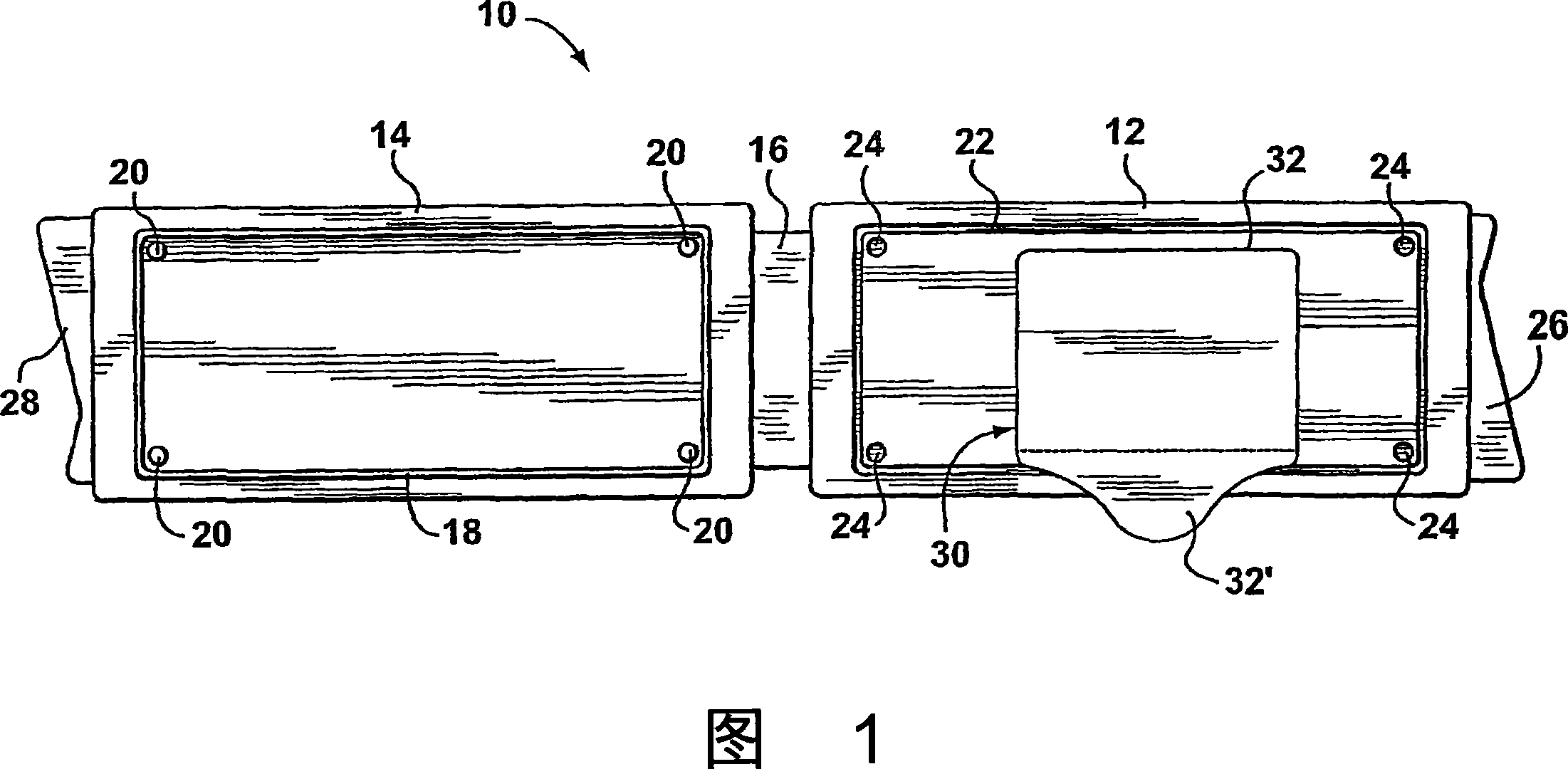
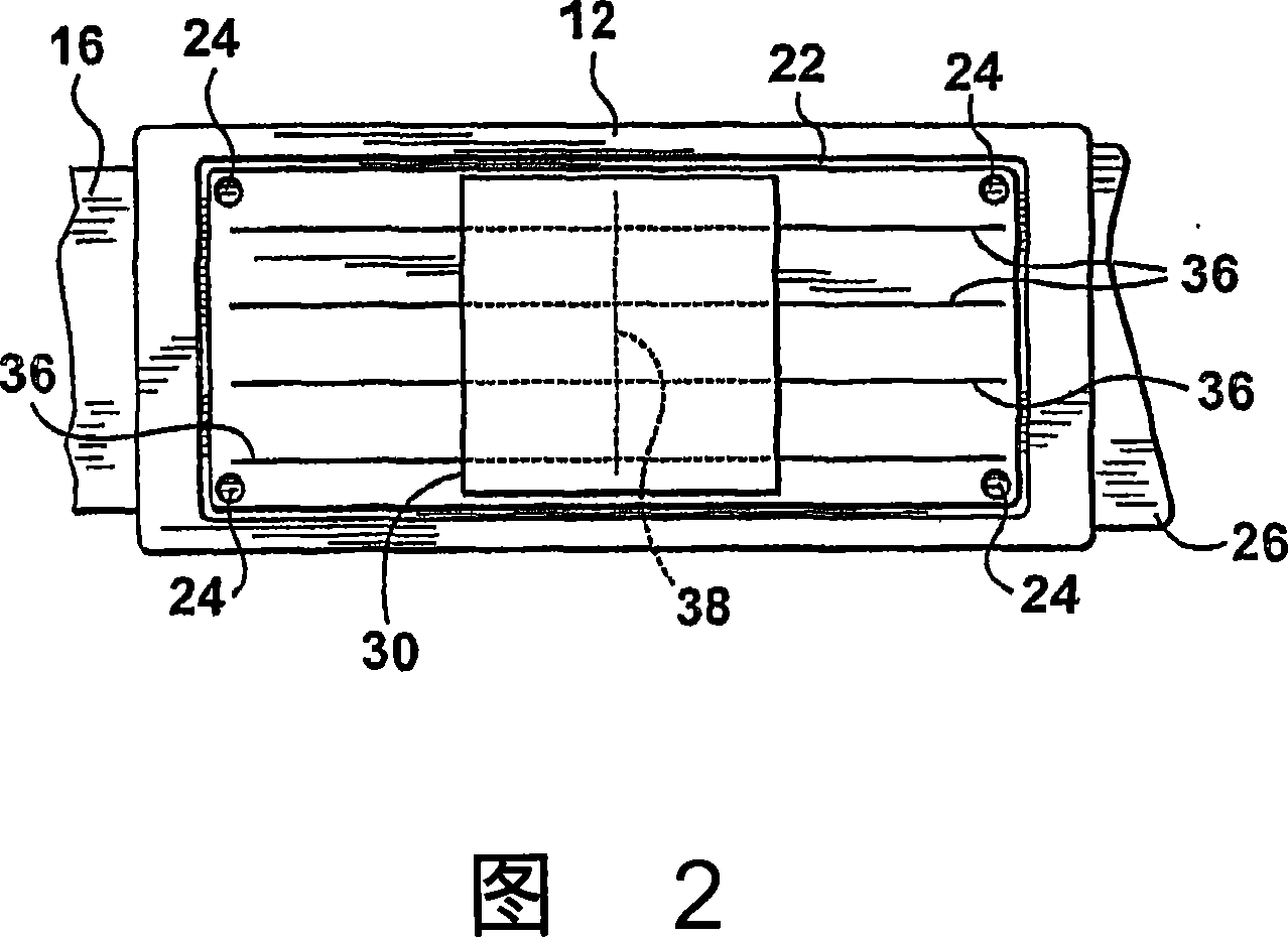
[0116] The sampling device shown in Figure 1 was used. The sampling device, indicated generally by the reference numeral 10, is made of plastic (polystyrene) and comprises a sampling member 12 connected to a closure member 14 by an integral hinge 16 . The closure 14 has a frame 18 and four pegs 20 that lock into side grooves 22 and four holes 24 of the sampling piece 12, respectively. Folding hinge 16 engages frame 18 with side groove 22 and peg 20 with hole 24, thereby ensuring that the two parts of device 10 are closed and sealed to prevent contamination of the interior surfaces by dust. The outer surface of closure 14 (not shown in Figures 1 and 2) has flat areas for affixing labels and barcodes to facilitate sample identification. Sampling member 12 and closure member 14 have handles 26 and 28 for opening device 10, respectively.
[0117] A double-coated pressure sensitive medical tape 30 with a protective release liner 32 made of kraft paper, product number #9877 of 3M,...
Embodiment 3
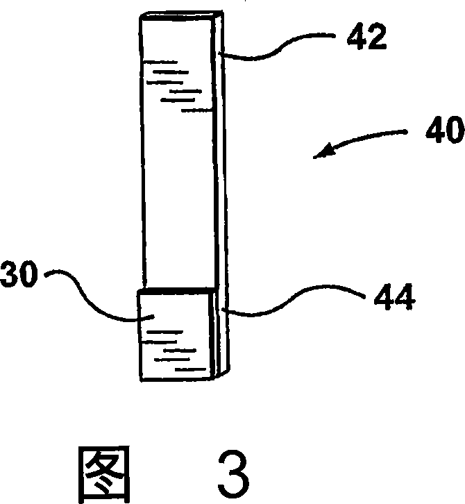
[0123] In order for many samples in Example 2 to be processed together, it is necessary to cut the test piece 40 into a uniform shape that matches the wells of a standard 96-well (8×12) microwell plate. Existing equipment can be used to add reagents to the wells of microplates and to wash the wells, with one requirement being to avoid reagent carryover between steps. The colored solution in the wells can be read directly in the final step of the assay using an existing spectrophotometer. However, during this process, the protruding parts of the test strips outside the wells and the fixtures that hold them prevent the instrument from loading and washing the wells. This results in the need for additional custom equipment for strip assays, and / or more manual steps than conventional microplate assays.
[0124] Batch processing of a large number of samples can be accomplished by cutting a small disc 50 (see, FIG. 4 ) from one side 52 of the sampling device, the disc 50 having an a...
PUM
 Abstract
Description
Claims
Application Information