Stent with auxiliary treatment structure

a technology of auxiliary treatment structure and stent, which is applied in the field of medical devices, can solve the problems of sudden closure of the vessel, ischemic injury, stroke or myocardial infarction, death or disability of tens of thousands of people, etc., and achieve the effect of reducing the turbulence of fluid flow

Inactive Publication Date: 2006-04-20
LIM WALTER K
View PDF42 Cites 100 Cited by
  • Summary
  • Abstract
  • Description
  • Claims
  • Application Information

AI Technical Summary

Benefits of technology

[0024] The device of the present invention has means for delivery of a therapeutic agent or agents to a stenosed site in a body lumen. The device includes an open-ended cylindrical body carried on a distal end of a catheter for insertion into the body lumen and placement at the stenosed site. The cylindrical body is movable between a collapsed position for insertion into the body lumen, and a radially expanded position pressed against the wall of the body lumen. In one embodiment, the device comprises a stent for permanent implantation, and the body sidewall is formed by a plurality of interconnected struts or elements defining openings therebetween, and at least one elongate ribbon is attached to an outer surface thereof for carrying a therapeutic agen

Problems solved by technology

Vascular disease leads to death or disability for tens of thousands of people each year in the United States alone.
More severe blockage of blood vessels in such individuals often leads to hypertension, ischemic injury, stroke, or myocardial infarction.
However, a limitation associated with PTCA is the abrupt closure of the vessel that may occur immediately after the procedure, and restenosis, which occurs gradually following the procedure and refers to the re-narrowing of an artery after an initially successful angioplasty.
Additionally, restenosis is a chronic problem in patients who have undergone saphenous vein bypass grafting.
Post-angioplasty closure of the vessel, both immediately after PTCA (acute reocclusion) and in the long term (restenosis), is a major difficulty associated

Method used


Image

  • Stent with auxiliary treatment structure
  • Stent with auxiliary treatment structure
  • Stent with auxiliary treatment structure

Examples


first embodiment

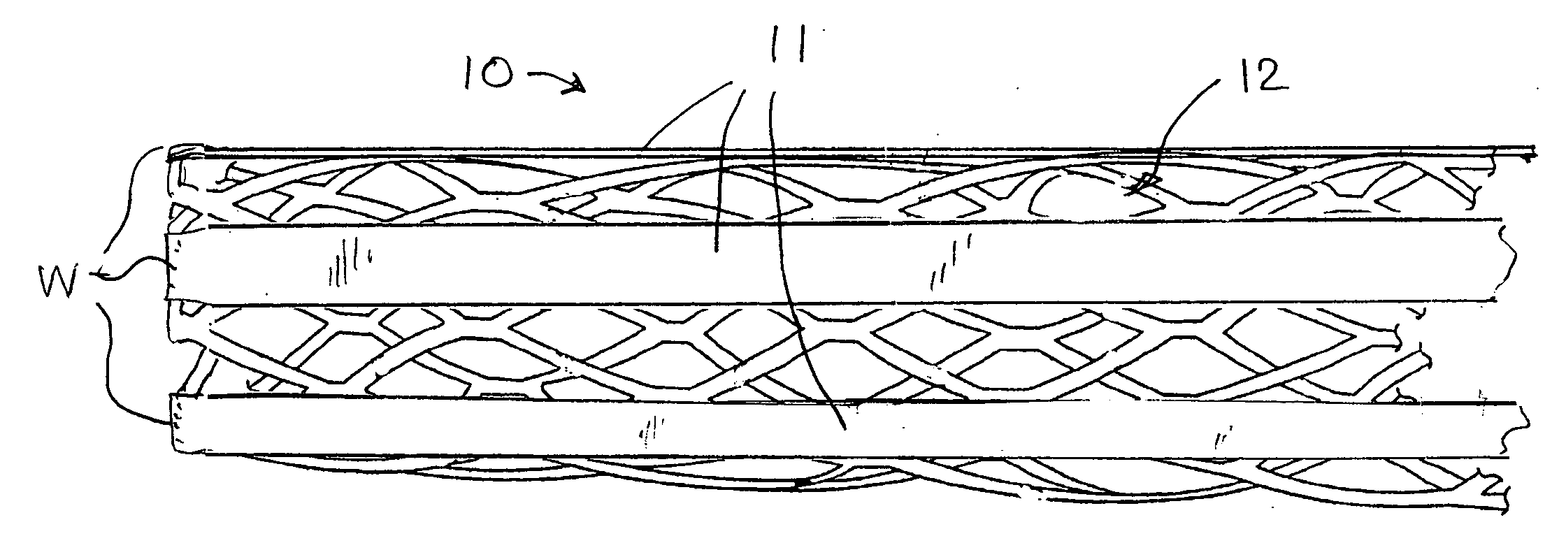
[0061] a stent with auxiliary treatment structure according to the invention is shown generally at 10 in FIG. 1. In this embodiment, a plurality of relatively wide bands or ribbons 11 are attached at least at one end to one end of the stent 12, and extend generally straight and parallel to one another longitudinally of the stent. The stent may be of any suitable construction, and in the example shown is of the type depicted in FIG. 10.

[0062] In order to permit expansion of the stent, the ribbons preferably are attached to the stent at only one end. In some stent constructions, the ribbons may be attached to both ends of the stent, and when the stent is expanded radially, it can shrink axially to accommodate expansion, even with the ribbons attached to both ends of the stent. Attachment of the ribbons can be by welding or other means known in the art, as represented at W in FIG. 1. Although not shown, it should be understood that the following embodiments could be similarly secured. ...

second embodiment

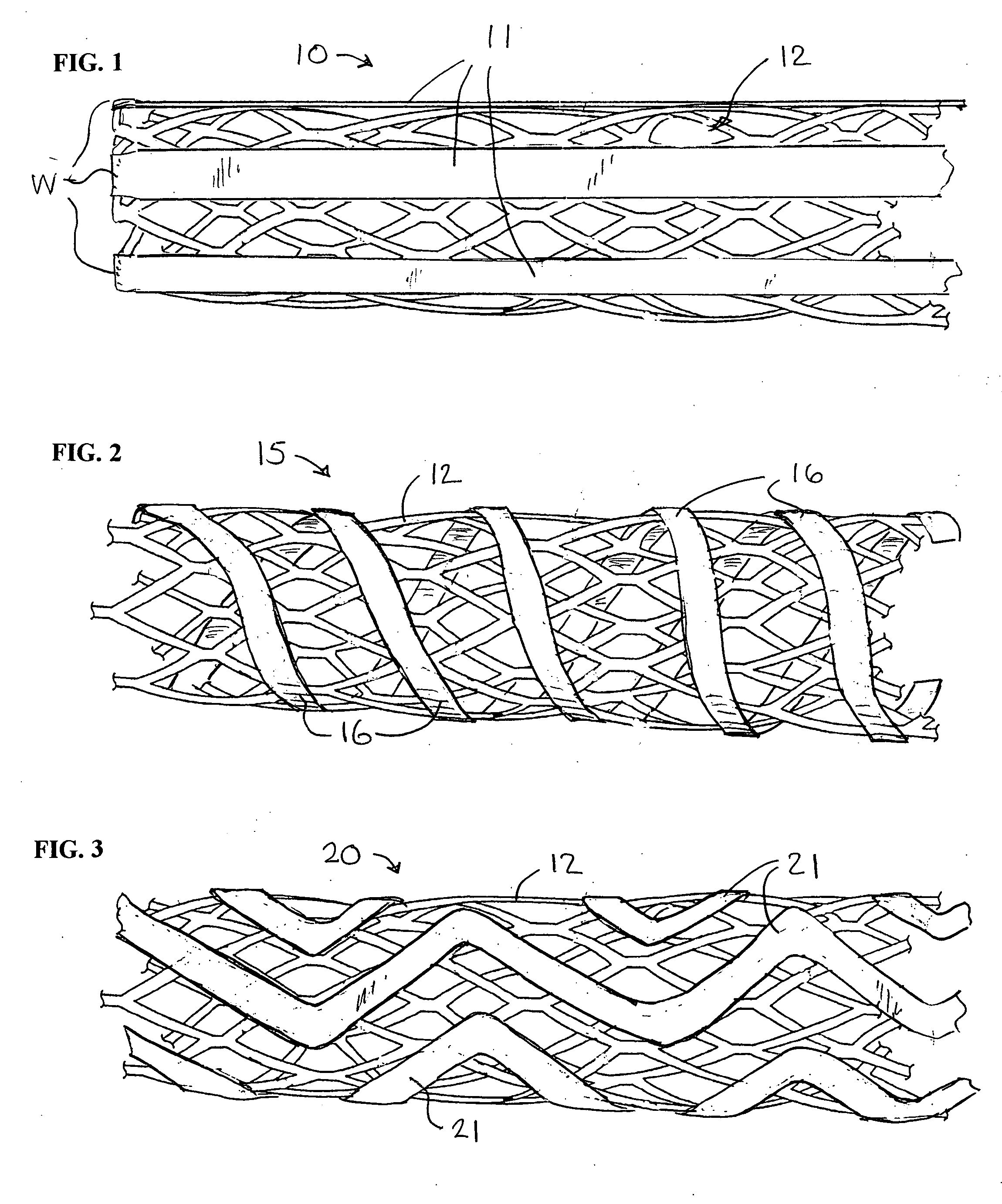
[0063] A second embodiment is shown at 15 in FIG. 2, wherein the ribbons 16 are wound around the stent 12 in a spiral pattern. As in the previous form, the ribbons can be attached at only one end or at both ends, depending upon the structure of the stent and the ability of the stent to undergo radial expansion with the ribbons attached.

third embodiment

[0064] A third embodiment is shown at 20 in FIG. 3, wherein the ribbons 21 are applied to the stent 12 in a zig-zag pattern. As in the previous form, the ribbons can be attached at only one end or at both ends, depending upon the structure of the stent and the ability of the stent to undergo radial expansion with the ribbons attached.

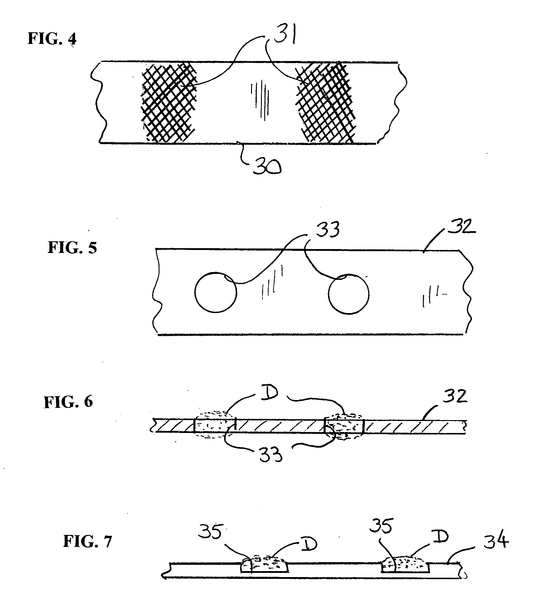
[0065]FIG. 4 depicts a ribbon 30 having roughened or textured areas 31 on its surface to provide a surface for enhanced mechanical bonding of a drug or other beneficial agent to the surface of the ribbon.

[0066]FIGS. 5 and 6 depict a ribbon 32 having openings or holes 33 formed through it to provide a means for applying a drug or other beneficial agent D to the ribbon.

[0067]FIG. 7 depicts a ribbon 34 having recesses or depressions 35 formed in the surface to provide a means for applying a drug or other beneficial agent D to the ribbon.

[0068]FIGS. 8 and 9 depict a section 36 of a stent body or a ribbon made of interwoven strands of material 37 and 38. ...


PUM


Abstract

A medical device for treatment of a stenosed body lumen, includes an open-ended cylindrical body carried on a distal end of a catheter for insertion of the device into the body lumen and placement at the stenosed site. The cylindrical body is movable between a collapsed position for insertion into the body lumen, and a radially expanded position pressed against the wall of the body lumen. In one embodiment the body sidewall is formed by a plurality of interconnected struts or elements defining openings therebetween, and at least one elongate ribbon is attached to an outer surface thereof for carrying a therapeutic agent. In another embodiment, the body is formed of interwoven elements defining a mesh-like structure, and the elements may comprise dissimilar materials, such as, e.g., copper and silver. In a further embodiment the body is formed of layers of different materials such as, e.g., copper, silver, and/or steel, laminated together. In a still further embodiment the device is designed for temporary placement of the catheter and body in a body lumen for treatment of a stenosed site, after which the catheter and body are withdrawn. In all forms the body may have an outwardly flared inlet end to reduce turbulence of fluid flowing through it, and/or a gel-like coating of a cholesterol-dissolving or blood clot dissolving agent may be placed on the device.

Description

[0001] This application claims the benefit of U.S. provisional patent application Ser. Nos. 60 / 619,233, filed Oct. 15, 2004, and 60 / 701,897, filed Jul. 22, 2005.BACKGROUND OF THE INVENTION [0002] 1. Field of the Invention [0003] The present invention relates to medical devices, and in particular to drug delivery stents, and to means for treatment of vascular disease at sites previously stented or previously unstented. [0004] 2. Description of the Related Art [0005] Vascular disease leads to death or disability for tens of thousands of people each year in the United States alone. It is caused by progressive blockage, or stenosis, of the blood vessels that perfuse the heart and other major organs. More severe blockage of blood vessels in such individuals often leads to hypertension, ischemic injury, stroke, or myocardial infarction. Atherosclerotic lesions, which limit or obstruct coronary blood flow, are the major cause of ischemic heart disease. [0006] The therapeutic alternatives a...

Claims


Application Information

Patent Timeline
IPC IPC(8): A61F2/06
CPCA61F2/07A61F2/91A61F2/915A61F2002/075A61F2230/0091A61F2250/0068A61F2/90A61F2210/0076A61F2002/91533
Inventor KRAUSE, ARTHUR A.LIM, WALTER K.
Owner LIM WALTER K
Why Eureka
Try Eureka