

Ac motor decelerating method and inverter device
An AC motor, voltage inverter technology, applied in the direction of AC motor acceleration/deceleration control, AC motor control, motor/generator/inverter limiter, etc., can solve the problem of increasing loss and increasing the excitation current of induction motor 308 And other issues
- Summary
- Abstract
- Description
- Claims
- Application Information
AI Technical Summary
Problems solved by technology
Method used
Image

Examples
Embodiment 1
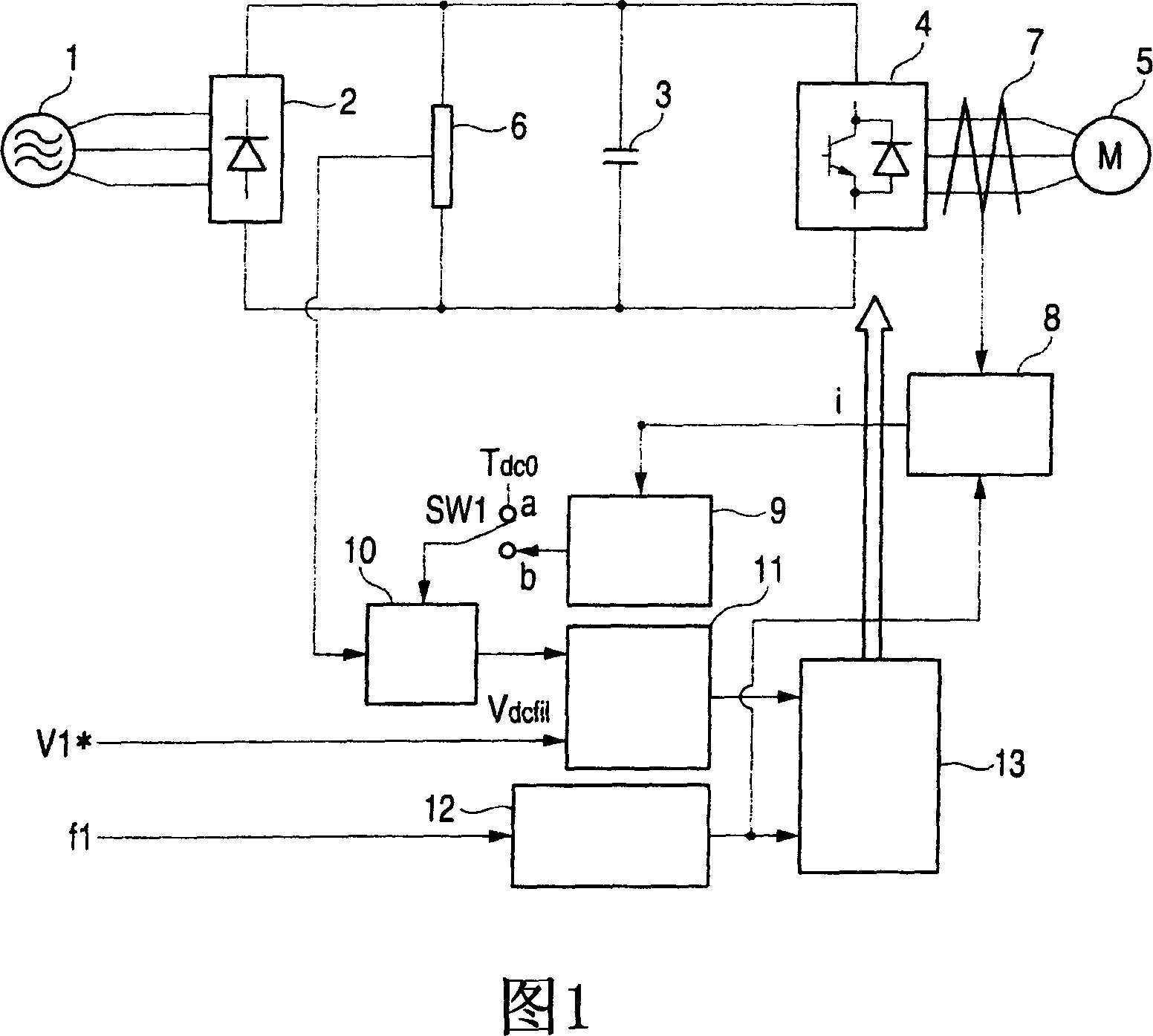
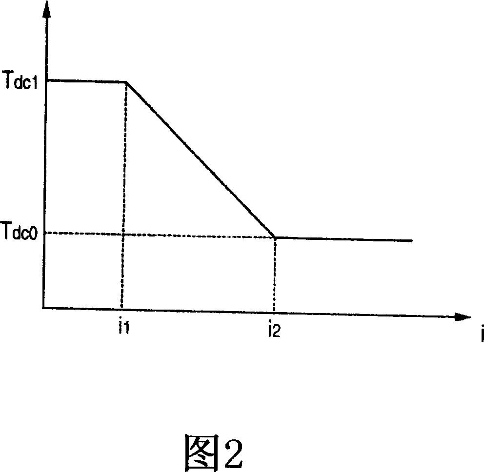
[0266] FIG. 1 shows a block diagram of a first embodiment of an inverter device to which the method of the present invention is applied, and FIG. 2 shows an example of a time constant adjusting section. The control device for an induction motor according to this embodiment includes an AC power source 1, a frequency converter section 2, a capacitor 3, an inverter section 4, an AC motor 5, a DC bus voltage detector 6, a current detector 7, a current converter 8, Time constant adjustment section 9, filter section 10, voltage correction section 11, frequency / phase converter 12, PWM calculation section 13, and switch SW1. The frequency converter section 2 of the inverter device rectifies the AC voltage of the AC power source 1, thereby converting it into a DC voltage. The capacitor 3 smoothes the DC voltage converted by the frequency converter section 2 . The inverter section 4 controls the power elements by PWM control, thereby converting the direct current into alternating curre...
Embodiment 2
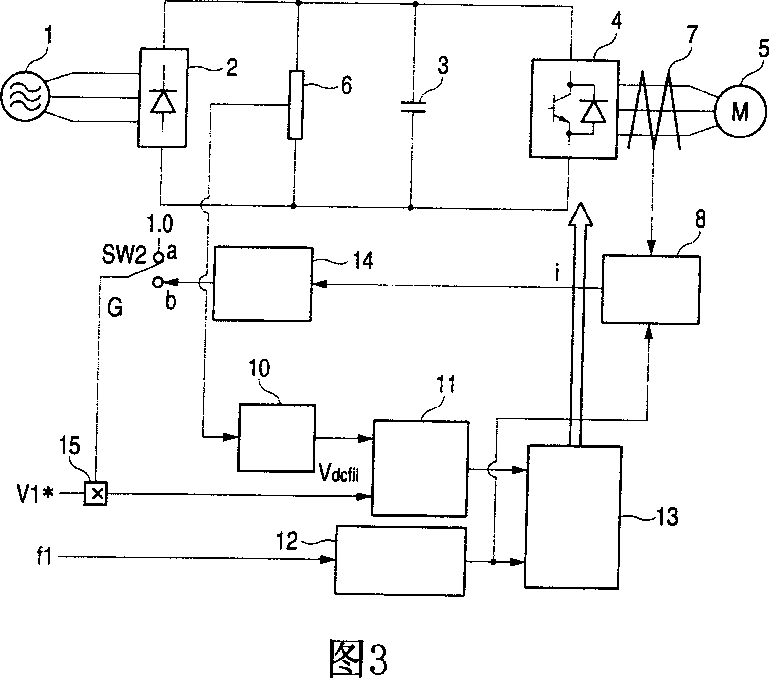
[0270] FIG. 1 shows a block diagram of a second embodiment of an inverter device to which the method of the present invention is applied, and FIG. 4 shows an example of a gain adjustment section. The control device for an induction motor according to this embodiment includes an AC power source 1, a frequency converter section 2, a capacitor 3, an inverter section 4, an AC motor 5, a DC bus voltage detector 6, a current detector 7, a current converter 8, filter section 10, voltage correction section 11, frequency / phase converter 12, PWM calculation section 13; gain adjustment section 14, multiplier 15, and switch SW2. The frequency converter section 2 of the inverter device rectifies the AC voltage of the AC power source 1, thereby converting it into a DC voltage. The capacitor 3 smoothes the DC voltage converted by the frequency converter section 2 . The inverter section 4 controls the power elements using PWM control to thereby convert direct current into alternating current...
Embodiment 3
[0274] Fig. 5 shows a block diagram of a third embodiment of an inverter device applying the method of the present invention, and Fig. 6 shows an example of a gain calculator. The control device for an induction motor according to this embodiment includes an AC power source 1, a frequency converter section 2, a capacitor 3, an inverter section 4, an AC motor 5, a DC bus voltage detector 6, a current detector 7, a current converter 8, Filter section 10, voltage correction section 11, frequency / phase converter 12, PWM calculation section 13, gain calculator 16, multiplier 15, and switch SW3. The frequency converter section 2 of the inverter device rectifies the AC voltage of the AC power source 1 to thereby convert it into a DC voltage. The capacitor 3 smoothes the DC voltage converted by the frequency converter section 2 . The inverter section 4 controls the power elements by PWM control to thereby convert direct current into alternating current having an arbitrary frequency a...
PUM
 Abstract
Description
Claims
Application Information