A plasma display and its manufacture method

A technology of plasma display and manufacturing method, applied in the direction of cold cathode manufacturing, electrode system manufacturing, discharge tube/lamp manufacturing, etc., can solve the problems of production yield decline, damage, unfavorable installation, etc., to reduce manufacturing time and reduce manufacturing cost. cost, productivity improvement effect

Inactive Publication Date: 2007-05-16
LG ELECTRONICS(NANJING) PLASMA CO LTD
View PDF0 Cites 0 Cited by
  • Summary
  • Abstract
  • Description
  • Claims
  • Application Information

AI Technical Summary

Problems solved by technology

However, it is necessary to increase the process of installing the getter chamber in order to install the getter, which leads to a decrease in production yield, and therefore, there is a problem that the manufacturing cost of the PDP increases.
[0015] The getter chamber is a structure protruding from the back of the display panel. This structure is not conducive to the installation of stru

Method used


Image

  • A plasma display and its manufacture method
  • A plasma display and its manufacture method
  • A plasma display and its manufacture method

Examples


Embodiment Construction

[0032] Hereinafter, the present invention will be described in detail with reference to the accompanying drawings.

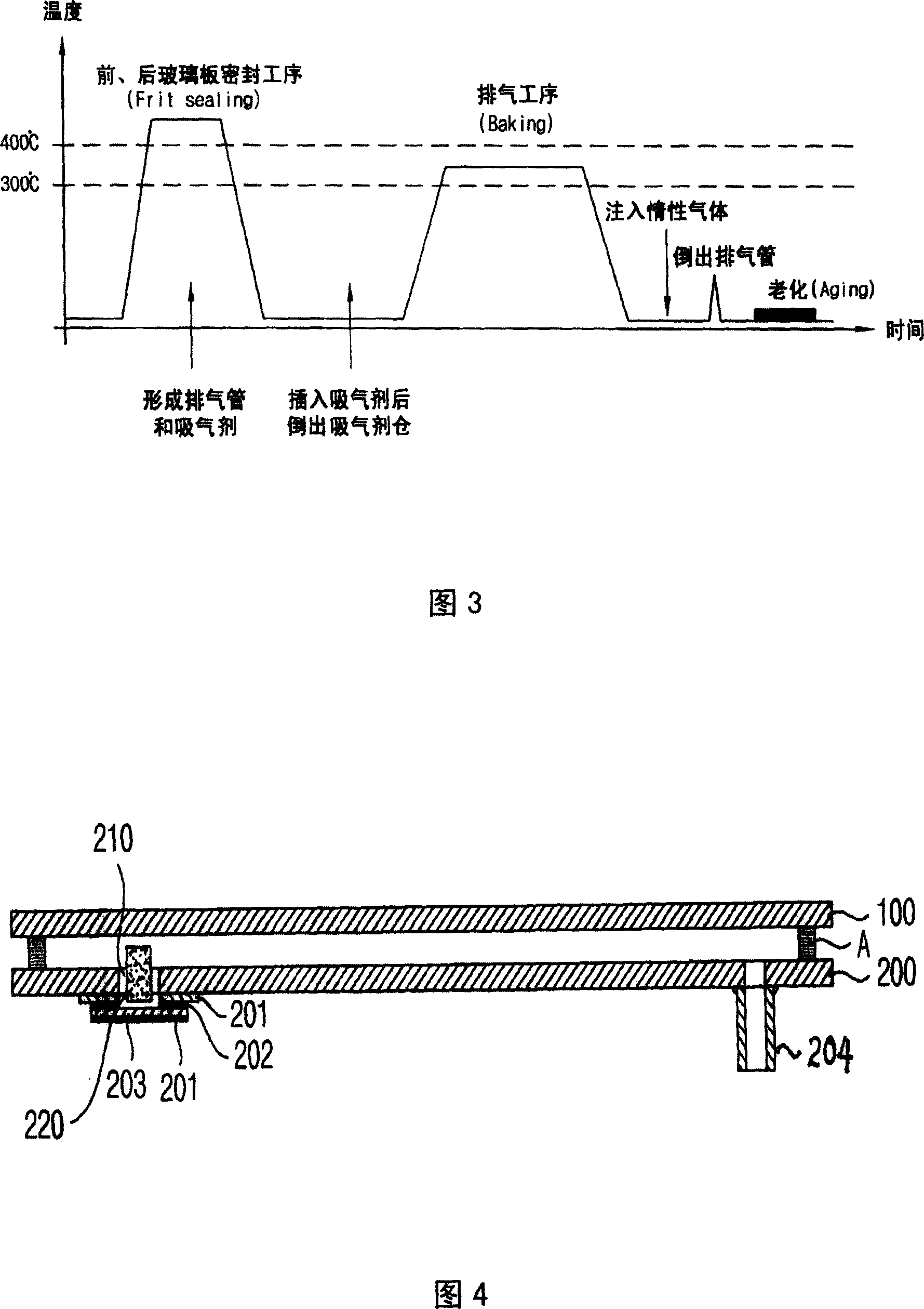
[0033] Fig. 4 is a schematic sectional view of the PDP of the present invention. As shown in FIG. 4 , the PDP of the present invention consists of a front glass plate 100 and a rear glass plate 200 that can display images arranged at a certain distance and are bonded together by a support glass plate A parallel to each other.

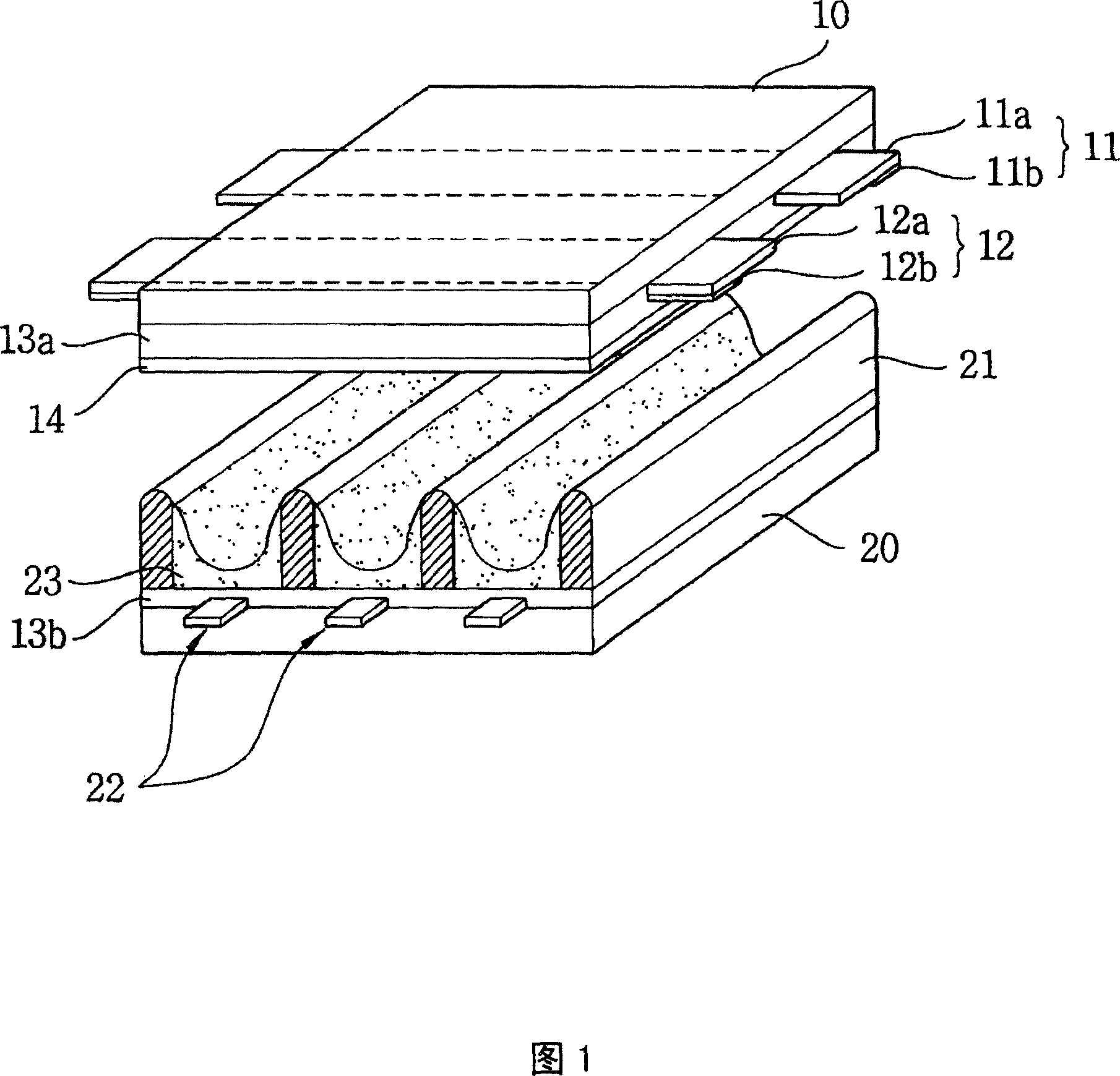
[0034] Since the structure of the front glass plate 100 and the rear glass plate 200 of the present invention is the same as the structure of the front glass plate 10 and the rear glass plate 20 of the conventional PDP, it will not be described in detail here.

[0035] Only the area where the getter is inserted on the rear glass plate, that is, the getter insertion hole 210 is provided on the outer side of the rear glass plate and the plasma non-discharge area, and the spherical getter is inserted into the getter insertion hole 210 220. ...


PUM


Abstract

The manufacture method for a plasma display comprises: with the plasma display set in a board to remove gas impurity, in the glass plates near the getter, setting inserting hole on the non-discharge area for the getter; near these holes, and arranging non-crystal silicon attached with conductive material and soda-lime glass attached with conductive material for sealing. Besides, the manufacture also includes: using glass plates to bond and seal, discharging impurity in display panel, and injecting the discharging gas.

Description

technical field [0001] The present invention relates to a plasma display and a manufacturing method thereof, in particular to a plasma display equipped with a getter to remove gas impurities in the plasma display manufacturing process and a manufacturing method thereof. Background technique [0002] In general, a plasma display (hereinafter referred to as PDP) is a flat-panel display element that introduces direct current (DC) or alternating current (AC) voltage to its electrodes to cause gas discharge between the electrodes, and then emits light from ultraviolet rays to make phosphors emit light to display images. . [0003] FIG. 1 is a schematic diagram of the structure of an existing AC-type PDP device. As shown in the figure, a PDP is composed of a display surface for displaying images, that is, a front glass plate 10 and a rear glass plate 20 forming the back of the display. The two plates are combined in parallel and have a certain distance. Sustain electrodes 11, 12...

Claims


Application Information

Patent Timeline
IPC IPC(8): H01J17/49H01J17/24H01J9/39H01J9/00H01J9/395H01J11/52
Inventor 李范周
Owner LG ELECTRONICS(NANJING) PLASMA CO LTD
Why Eureka
Try Eureka