Single fiber and multi-core fiber coupler and fused biconic taper coupling method thereof

A technology of multi-core optical fiber and single-core optical fiber, applied in the field of optical fiber, can solve the problems of large volume, unsolved coupling between single-core optical fiber and multi-core optical fiber, poor reliability, etc.

Inactive Publication Date: 2007-05-23
HARBIN ENG UNIV
View PDF0 Cites 43 Cited by
  • Summary
  • Abstract
  • Description
  • Claims
  • Application Information

AI Technical Summary

Problems solved by technology

The disadvantages of this kind of optical passive device composed of traditional optical discrete components are: large volume, high quality, loose structure, poor reliability, and incompatibility with optical fibers
For example, the patent No. 96116575 is a fused-cone high-density wavelength division multiplexer, which includes multiple 1×2 or 2×2 fiber couplers, but these technologies do not solve the problem of single-core fiber and multi-core fiber coupling. The problem

Method used


Image

  • Single fiber and multi-core fiber coupler and fused biconic taper coupling method thereof
  • Single fiber and multi-core fiber coupler and fused biconic taper coupling method thereof
  • Single fiber and multi-core fiber coupler and fused biconic taper coupling method thereof

Examples


Embodiment 1

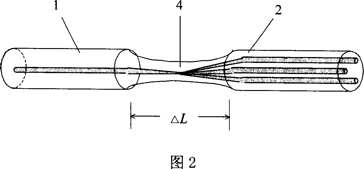
[0026] In this embodiment, the coating layer at one end of a single-core optical fiber and a multi-core optical fiber is stripped off, and after stripping, the end face of the optical fiber is cleaned and cut to form a smooth end face, and then directly fused at the stripped place by an optical fiber welding machine, and welded. Heating at the point to implement melting taper, and monitor the optical power. When the waist of the cone is thinned to the predetermined splitting ratio achieved by the distribution of optical power by the cone, the taper is stopped to make single-core fiber and multi-core fiber coupler. .

[0027] The method of fusion splicing taper coupling is:

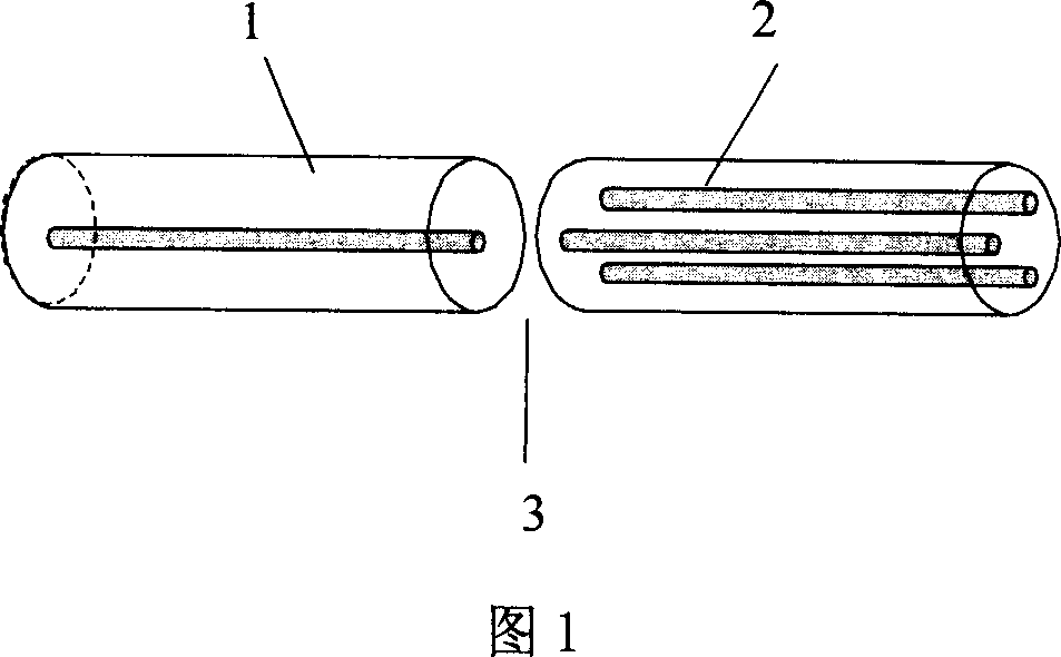
[0028] 1. Select the single-core optical fiber 1 to be coupled, peel off the coating layer at one end, and then clean and cut out a flat fiber end face; 1 is a single-core optical fiber, 2 is a multi-core optical fiber, and 3 is two sections of optical fiber for welding Join the ends.

[0029] 2. Prepare...

Embodiment 2

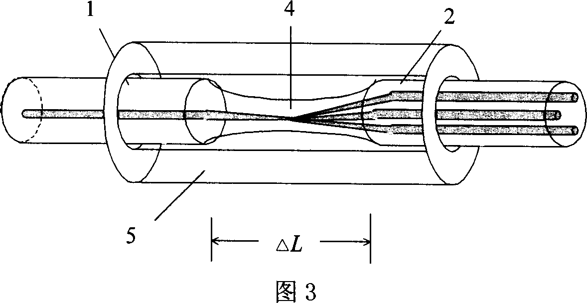
[0036] In this embodiment, the coating layer at one end of a single-core optical fiber and a multi-core optical fiber is stripped off, and after stripping, the end face of the optical fiber is cleaned and cut to form a smooth end face, and then directly fused at the stripped place by an optical fiber welding machine, and welded. Heating at the point to implement melting taper, and monitor the optical power. When the waist of the cone is thinned to the predetermined splitting ratio achieved by the distribution of optical power by the cone, the taper is stopped to make single-core fiber and multi-core fiber coupler. .

[0037] The method of fusion splicing taper coupling is:

[0038] 1. Select the single-core optical fiber 1 to be coupled, peel off the coating layer at one end, and then clean and cut out a flat fiber end face; 1 is a single-core optical fiber, 2 is a multi-core optical fiber, and 3 is two sections of optical fiber for welding Join the ends.

[0039] 2. Prepare...


PUM


Abstract

The invention discloses a single-core and multi-core fiber coupler and fiber access into rafah cone coupling method. It peels the ending coating layer of a single-core optical fibers and a multi-core fiber, direct financial with the fiber welding machine in stripping department, received and in the implementation of solder joint heating department fused biconical taper, monitoring optical power, when cone waist rafah small cone of light power distribution to the target, spectrophotometer stopping widening cone. The method is the technical characteristics of single-core fiber and multi-core fiber fusion welding, the solder joint implemented fused biconical taper, thus forming a cone of light energy distribution, optical power of distribution. The method can be single-core optical fiber distribution of power coupled multi-core optical fiber to each core, or multi-core fiber coupling of light waves to single-core fiber, to achieve optical spectrophotometer and cooperation functions.

Description

(1) Technical field [0001] The invention relates to the field of optical fiber technology, in particular to a single-core optical fiber and multi-core optical fiber coupler and a coupling method for fusing and splicing the taper. (2) Background technology [0002] Optical directional coupler, also known as optical directional coupler, is a passive device for splitting, combining, inserting and distributing optical signals. [0003] In the manufacturing method of optical passive devices, traditional optical methods were mostly used in the early days. The disadvantages of this optical passive device composed of traditional optical discrete components are: large volume, high quality, loose structure, poor reliability, and incompatibility with optical fibers. So people have turned to the research of all-fiber optical passive devices, and the research on all-fiber directional couplers is the most. Base. [0004] There are three types of manufacturing processes for all-fiber di...

Claims


Application Information

Patent Timeline
Patent Type & Authority Applications(China)
IPC IPC(8): G02B6/255G02B6/24
Inventor 苑立波刘志海杨军
Owner HARBIN ENG UNIV
Why Eureka
Try Eureka