Multi-degree of freedom spherical traveling wave-type ultrasonic motor

A technology of ultrasonic motors and spherical motors, applied in the direction of generators/motors, piezoelectric effect/electrostrictive or magnetostrictive motors, electrical components, etc., can solve problems such as complex structure, limited practicality, and difficult implementation. Achieve the effects of simplified mechanical structure, simple overall structure, and convenient attitude control

Inactive Publication Date: 2007-05-30
ZHEJIANG UNIV
View PDF0 Cites 4 Cited by
  • Summary
  • Abstract
  • Description
  • Claims
  • Application Information

AI Technical Summary

Problems solved by technology

However, the electromagnetic ball motor needs to form a spherical rotating magnetic field, which makes the structure very complicated and difficult to realize. At present, the performance of the electromagnetic ball motor realized at home and abroad is relatively poor, and it is not practical. The multi-degree-of-freedom ultrasonic motor has low speed, high torque, fast response, It has the characteristics of high precision and direct drive, and has the incomparable advantages of electromagnetic induction motors. In recent years, it has been successfully applied to abdominal surgery, shoulder, wrist and knee joints on prosthetics, two-degree-of-freedom CCD (monitoring head) pan-tilt drive and robots. Therefore, it is necessary to develop a spherical ultrasonic motor with compact structure, low speed and high torque.

Method used


Image

  • Multi-degree of freedom spherical traveling wave-type ultrasonic motor
  • Multi-degree of freedom spherical traveling wave-type ultrasonic motor

Examples


Embodiment Construction

[0019] The present invention will be further described below in conjunction with accompanying drawing.

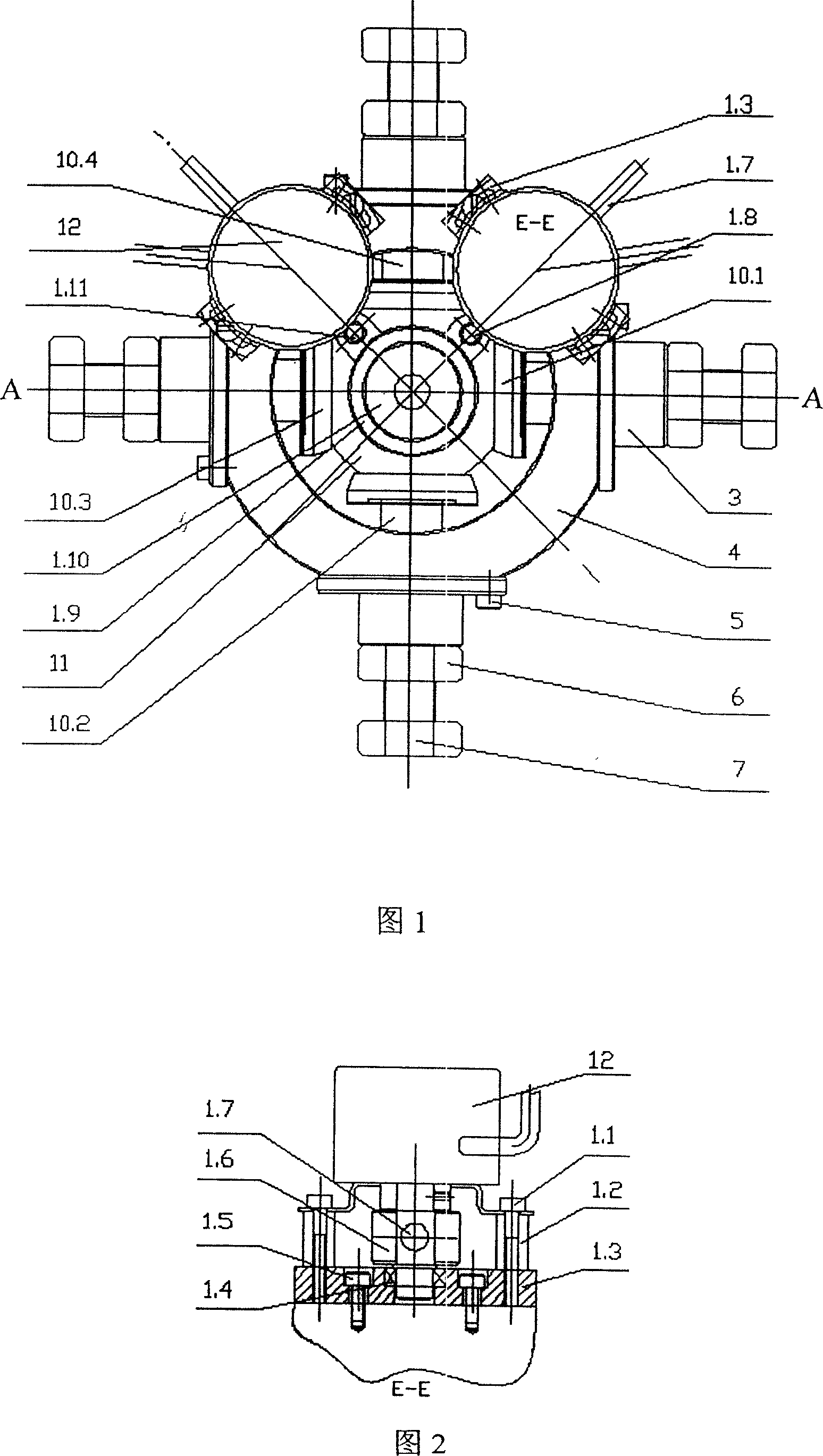
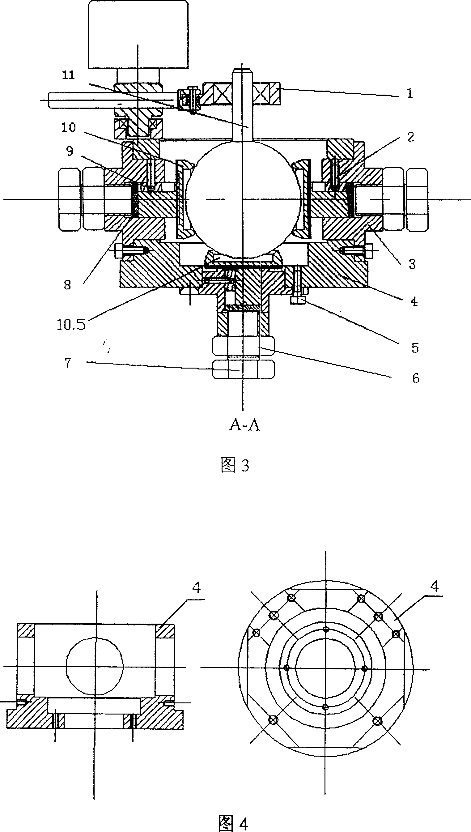
[0020] As shown in Fig. 1, Fig. 2, Fig. 3 and Fig. 4, the present invention installs a spherical motor rotor 11 in the motor body 4, and installs a traveling wave stator at the front, rear, left, right and bottom of the spherical motor rotor 11 10.1, 10.2, 10.3, 10.4, 10.5 The inner spherical surface is matched with the spherical motor rotor 11, the five traveling wave stators are installed on the motor body 4 through their respective stator connecting parts, and the output shaft of the spherical motor rotor 11 is installed with mutual 90° attitude angle detection mechanism.

[0021] The stator connecting parts: each includes a stator connecting piece 3, an adjusting screw 6 and a nut 7; the tail of the traveling wave stator is loaded into the stator connecting 3, an elastic body 8 is installed between the tail and the adjusting bolt 6, and the stator is connected Part 3 i...


PUM


Abstract

This invention discloses one multiple freedom ball wave supersonic motor, which fixes one ball motor rotor in side television shell and separately fixes one wave stator matched with ball motor rotor on its front, back, left, right and bottom parts, wherein, five stators are separately fixed on television shell fixed with 90 degree position angle test structure on ball motor rotor output axis.

Description

technical field [0001] The invention relates to an ultrasonic motor, in particular to a multi-degree-of-freedom spherical traveling wave ultrasonic motor. Background technique [0002] Many phenomena in nature are driven by multiple degrees of freedom, such as human shoulders, wrists and hip joints, and eyeballs also rotate with two degrees of freedom. In addition, with the development of science and technology, electromechanical systems are becoming more and more complex, especially some precision devices have higher and higher requirements for motion, and single-degree-of-freedom drives can no longer meet the requirements, such as robots, camera systems, etc. also require multiple degrees of freedom drive. In these systems, if the movement of each degree of freedom is completed by a single-degree-of-freedom motor, it will inevitably result in complex mechanisms, bulky, bulky and poor dynamic performance of the moving parts. The multi-degree-of-freedom ultrasonic motor st...

Claims


Application Information

Patent Timeline
Patent Type & Authority Applications(China)
IPC IPC(8): H02N2/00G01C1/00
Inventor 郭吉丰沈润杰帅光举傅平王光庆潘建立
Owner ZHEJIANG UNIV
Why Eureka
Try Eureka