

Plasma processing apparatus and method
A plasma and processing device technology, which is applied in the field of plasma processing devices, can solve the problem that the etching selectivity ratio between Low-k film and SiC layer cannot be fully ensured, etc.
- Summary
- Abstract
- Description
- Claims
- Application Information
AI Technical Summary
Problems solved by technology
Method used
Image

Examples
Embodiment approach 1
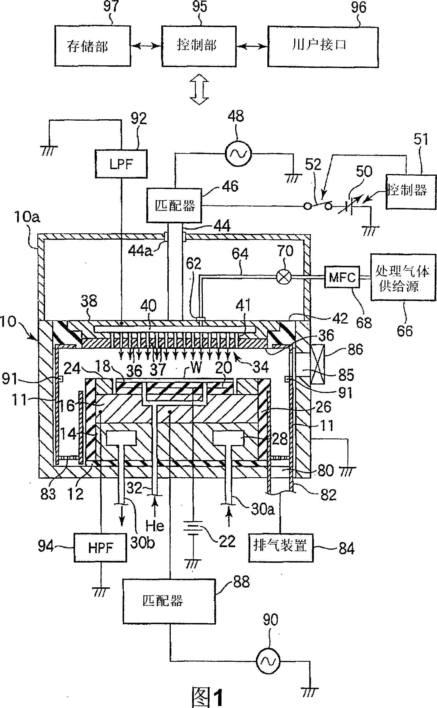
[0212] First, the first embodiment will be described. FIG. 1 is a schematic cross-sectional view showing a plasma etching apparatus according to a first embodiment of the present invention.
[0213] This plasma etching apparatus is configured as a capacitively coupled parallel plate plasma etching apparatus, and has a substantially cylindrical chamber (processing container) 10 made of, for example, aluminum whose surface is anodized. The chamber 10 is safety grounded.
[0214] At the bottom of the chamber 10 , a cylindrical susceptor support 14 is arranged via an insulating plate 12 made of ceramics or the like, and a susceptor 16 made of, for example, aluminum is provided on the susceptor support 14 . The susceptor 16 constitutes a lower electrode, and a semiconductor wafer W serving as a substrate to be processed is placed thereon.
[0215] An electrostatic chuck 18 that attracts and holds the semiconductor wafer W by electrostatic force is provided on the upper surface of...
Embodiment approach 2
[0362] Next, a second embodiment of the present invention will be described.
[0363] 34 is a schematic cross-sectional view showing a plasma etching apparatus according to a second embodiment of the present invention. In FIG. 34, the same components as those in FIG. 1 are denoted by the same reference numerals, and description thereof will be omitted.
[0364]In this embodiment, instead of the upper electrode 34 of the first embodiment, an upper electrode 34' having the following structure is provided. The upper electrode 34' is composed of a ring-shaped outer upper electrode 34a disposed opposite to the susceptor 16 at a predetermined interval, and a disk-shaped inner upper electrode 34b disposed radially inward of the outer upper electrode 34a in an insulated state. constitute. These are involved in the generation of plasma, and have a relationship in which the outer upper electrode 34 a is the main one and the inner upper electrode 34 b is the auxiliary one.
[0365] As...
no. 3 approach
[0408] In the third embodiment, components common to those in the first and second embodiments are denoted by the same symbols.
[0409] 40 is a schematic cross-sectional view showing a plasma etching apparatus according to a third embodiment of the present invention.
[0410] That is, it applies high-frequency (RF) power of, for example, 40 MHz for plasma generation from the first high-frequency power supply 88 to the susceptor 16 as the lower electrode, and supplies the susceptor 16 as the lower electrode from the second high-frequency power supply 90 . 16. A lower RF dual-frequency application type plasma etching apparatus for applying high-frequency (RF) power of, for example, 2 MHz for ion introduction. As shown in the figure, a variable DC power supply 50 is connected to the upper electrode 34 to apply Plasma etching apparatus with specified direct current (DC) voltage. This plasma etching apparatus will be described in detail using FIG. 41 .
[0411] This plasma etchi...
PUM
 Abstract
Description
Claims
Application Information