Ultrasonic diagnostic apparatus

A diagnostic device, ultrasonic technology, applied in the direction of acoustic wave diagnosis, infrasonic wave diagnosis, ultrasonic/sonic wave/infrasonic wave diagnosis, etc., can solve problems such as difficult detection, achieve the effect of suppressing aliasing and reliable screen display

Inactive Publication Date: 2007-06-06
OLYMPUS CORP
View PDF2 Cites 2 Cited by
  • Summary
  • Abstract
  • Description
  • Claims
  • Application Information

AI Technical Summary

Problems solved by technology

[0005] However, in the ultrasonic diagnostic apparatus described in the aforementioned Patent Document 1, since the occurrence of the above-mentioned aliasing is suppressed by enlarging the flow velocity range which is a preset velocity range of interest, the velocity corresponding to the velocity of a moving body other than the examination target The cutoff frequency of the filter processing that removes frequency components often increases with the expansion of the flow velocity range.
At this time, the speed range (removed speed range) in which the speed of the moving body other than the inspection target is removed by the filter processing is expanded by the expansion of the flow speed range, that is, the increase of the cutoff frequency. The problem that it becomes difficult to detect low-velocity components in the flow velocity range of the target

Method used


Image

  • Ultrasonic diagnostic apparatus
  • Ultrasonic diagnostic apparatus
  • Ultrasonic diagnostic apparatus

Examples


no. 1 approach

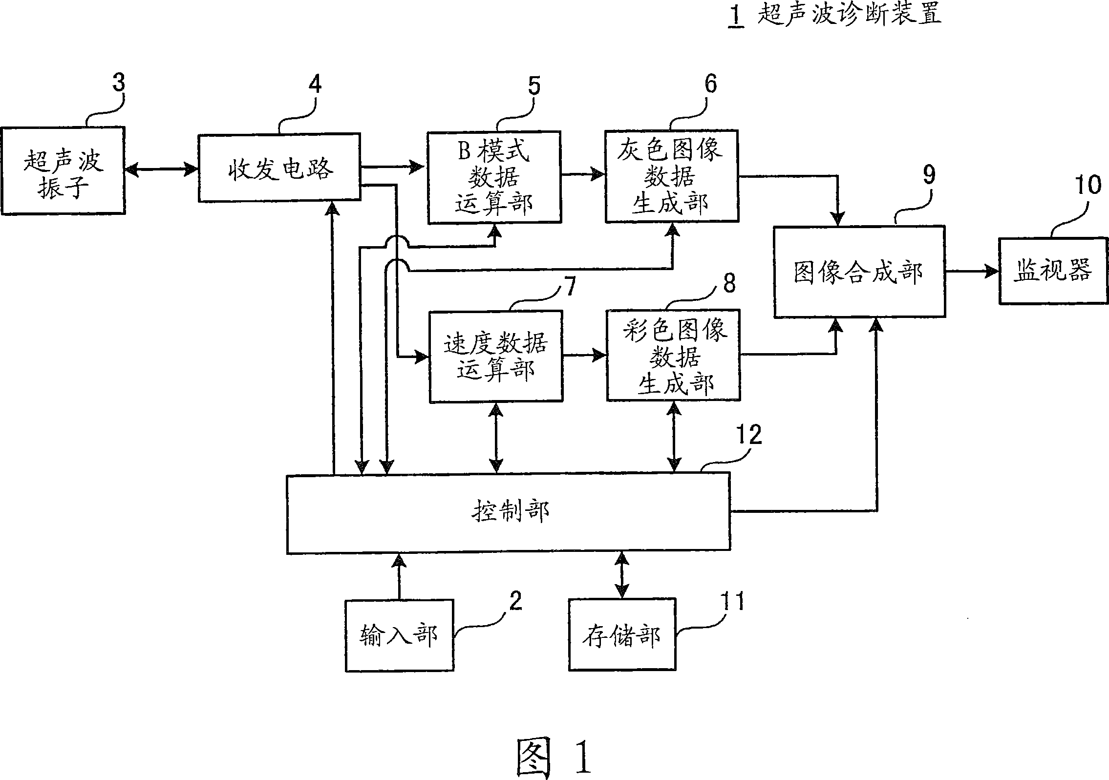
[0055] FIG. 1 is a block diagram illustrating a configuration example of an ultrasonic diagnostic apparatus as a first embodiment of the present invention. In FIG. 1, the ultrasonic diagnostic apparatus 1 has an input unit 2, an ultrasonic vibrator 3, a transceiver circuit 4, a B-mode data computing unit 5, a gray image data generating unit 6, a velocity data computing unit 7, a color image data generating unit 8, An image synthesis unit 9 , a monitor 10 , a storage unit 11 and a control unit 12 .

[0056] The input unit 2 is realized by using a keyboard, a touch panel, a trackball, a mouse, or a rotary switch singly or in combination, and is electrically connected to the control unit 12 . The input unit 2 receives various instruction information, such as instructing the start, end, or switching of operations performed by each component unit of the ultrasonic diagnostic apparatus 1, and the calculation process performed by each component unit of the ultrasonic diagnostic appar...

no. 2 approach

[0172] The second embodiment of the present invention will be described in detail below. In the above-mentioned first embodiment, each brightness or each hue of the color gradation data is assigned to all speeds within the detectable speed range ±Vr, and the colors corresponding to all speeds within the detectable speed range ±Vr However, in the second embodiment, it is configured that each luminance or each hue of the color gradation data is not classified for each speed outside the concerned speed range ±Vi and within the detectable speed range ±Vr. Instead, each brightness or each hue of the color scale data is allocated for each speed within the speed range ± Vi of interest, and the images of the color scale corresponding to all speeds within the speed range ± Vi of the interest are carried out. Show output.

[0173] FIG. 11 is a block diagram illustrating a configuration example of an ultrasonic diagnostic apparatus as a second embodiment of the present invention. This ...


PUM


Abstract

An ultrasonic diagnostic apparatus transmits ultrasound to an interior of a subject body and receives the ultrasound from the interior of the subject body to obtain plural pieces of ultrasound data, calculates a velocity of a moving body in the subject body as a velocity within a predetermined velocity range based on the plural pieces of ultrasound data, and generates and outputs a velocity image which indicates the calculated velocity as a velocity image of the moving body. The ultrasonic diagnostic apparatus includes an input unit which supplies information indicating a velocity range of interest of the moving body as an input, a velocity range setting control unit, and an image processing control unit. The velocity range setting control unit sets a variable detectable velocity range which is wider than the velocity range of interest and which covers the velocity range of interest as the predetermined velocity range based on the information supplied from the input unit. The image processing control unit allocates color scale data to each velocity within the detectable velocity range, and generates the velocity image based on the allocated color scale data and the calculated velocity.

Description

technical field [0001] The present invention involves multiple times of irradiating ultrasonic waves into the living body, receiving the echoes in sequence, repeating ultrasonic scanning according to the same sound ray direction, and generating and outputting the data indicated in the living body on the basis of multiple ultrasonic data obtained by the ultrasonic scanning. Ultrasonic diagnostic equipment for color images of the velocity of moving bodies moving in the body, that is, velocity images. Background technique [0002] Conventionally, an ultrasonic diagnostic device that performs ultrasound scans that irradiate ultrasonic waves into a living body and receives echoes thereof, generates and outputs an ultrasonic tomographic image in the living body and a speed image representing the speed of a moving body moving in the living body has been used as an ultrasonic diagnostic device that can Medical diagnostic devices that observe in real time a tomographic image of a reg...

Claims


Application Information

Patent Timeline
Patent Type & Authority Applications(China)
IPC IPC(8): A61B8/06
CPCA61B8/13A61B8/08A61B8/488G01S15/8979A61B8/06G01S7/52071G01S15/584
Inventor 宫木浩仲
Owner OLYMPUS CORP
Why Eureka
Try Eureka