Thermal-insulating binded composite wall with supporter

A thermal insulation composite and bundled technology, applied in thermal insulation, walls, passive houses, etc., can solve problems such as unsafe fire protection, difficulty in adapting to external walls, and rigidity of steel anchor bolts to adapt to safety requirements.

Inactive Publication Date: 2007-06-20
吴淑环
View PDF1 Cites 25 Cited by
  • Summary
  • Abstract
  • Description
  • Claims
  • Application Information

AI Technical Summary

Problems solved by technology

[0002] There are many problems in the current various external wall insulation technologies. In the final analysis, the contradiction between safety and insulation has not been solved, that is, the wall insulation with good safety is not good; the wall with good insulation is not safe, which is manifested in the structure. The main reason why the current wall insulation technology has these shortcomings is that it solves the connection between the insulation layer and the wall from the material, and does not rely on structural means to solve the problem of the connection between the insulation layer and the wall. The connection between the main body of the building and the base wall, so any technology that mixes thermal insulation materials with non-energy-saving materials, there will be thermal bridges in the concrete cornice boards and thermal bridges around the windows, and many blocks also have their own thermal bridges. It has a great impact on building energy saving, high cost, and it is impossible to achieve the low heat transfer coefficient of the wall
Some have installed insulation materials such as polyurethane on the large decorative panels produced by the factory, and used steel anchors to connect with the base wall, but this connection is too simple to adapt to the large horizontal wind pressure and large Due to the requirements of horizontal earthquake action, when the thicker insulation layer and the outer wall are heavily decorated, it may be difficult to meet the safety requirements because the rigidity of the steel anchor bolt is too small, and it is even more difficult to combine with various masonr...

Method used


Image

  • Thermal-insulating binded composite wall with supporter
  • Thermal-insulating binded composite wall with supporter
  • Thermal-insulating binded composite wall with supporter

Examples


specific Embodiment approach 1

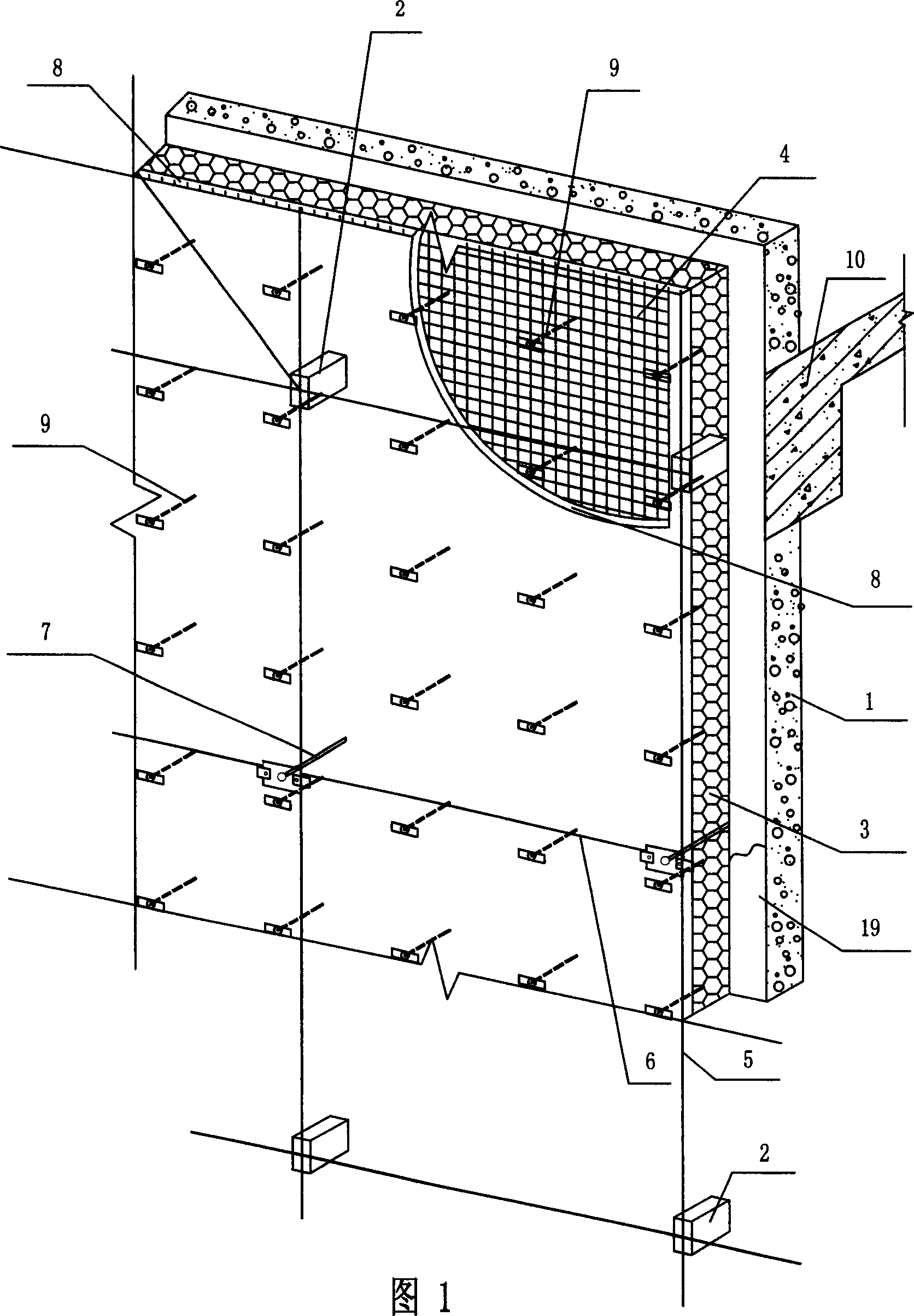
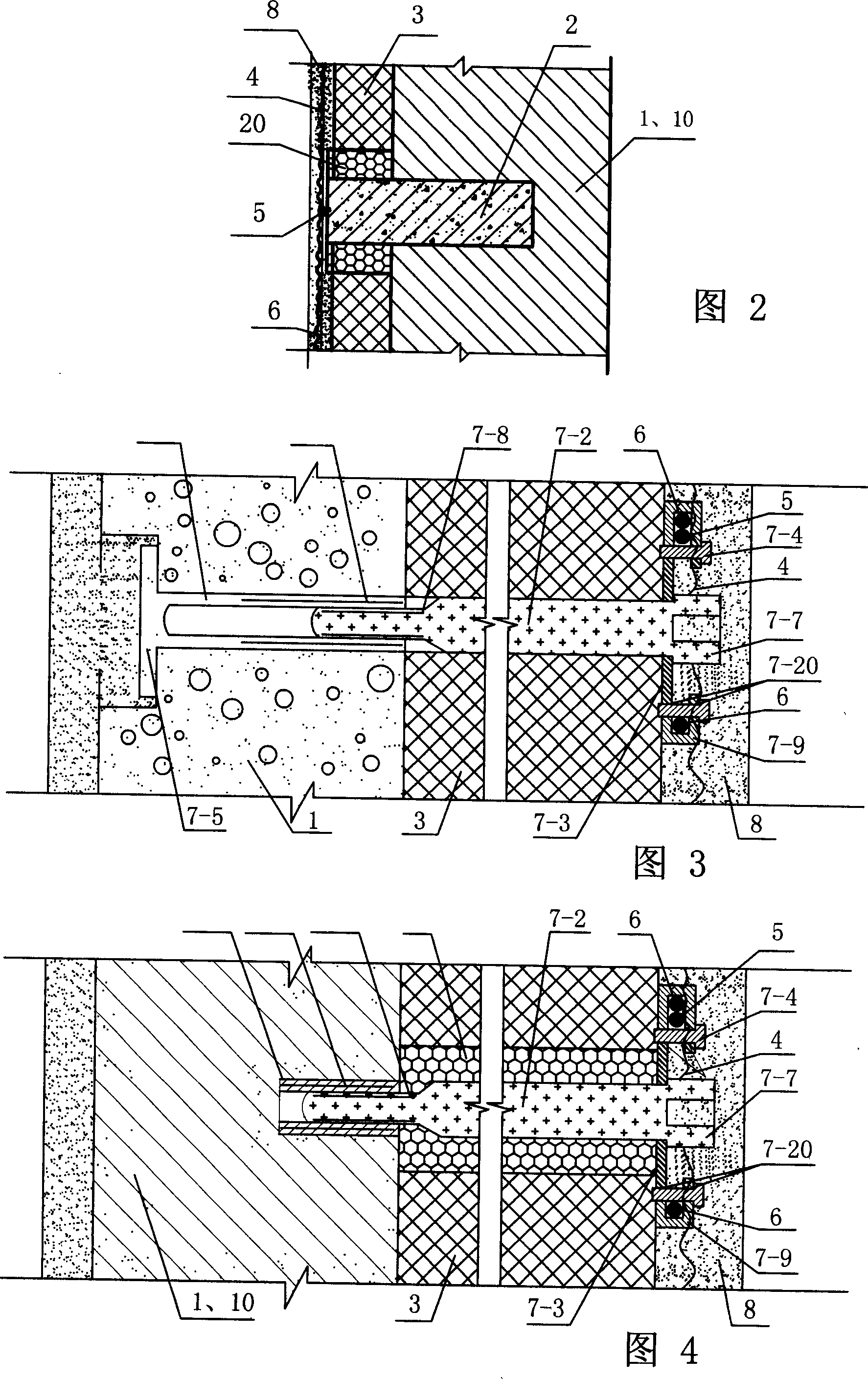
[0005] Specific embodiment one: (see Fig. 1, Fig. 2) this embodiment consists of base wall 1, concrete cantilever beam support 2, insulation layer 3, metal mesh 4, vertical steel bars 5, horizontal connecting rods 7, outer The protective layer 8, plastic expansion nails 9 and concrete components 10 of the main building structure, the concrete components 10 of the main building structure include concrete ring beams, concrete girders, concrete columns, concrete walls, concrete lintels, concrete The foundation, the concrete balcony slab, the concrete window side wall slab or the concrete window sill slab connected with the concrete of the upper and lower floors, the inner end of the concrete cantilever beam support member 2 is fixed on the inside or outer surface of the concrete member 10 of the main building structure with steel parts Fixed, or fixed in the base wall 1 of the load-bearing masonry, the inner end of the horizontal connecting rod 7 is fixed in the base wall 1 or the...

specific Embodiment approach 2

[0007]Specific embodiment two (referring to Fig. 1, Fig. 2): the difference of this embodiment and specific embodiment one is, in outer protective layer 8, increase horizontal horizontal steel bar 6, horizontal horizontal steel bar 6 two ends and concrete cantilever beam support member 2 The pre-embedded steel plate at the outer end is welded or fixed on the outer end of the horizontal connecting rod 7, and the horizontal and transverse reinforcement can be set to increase the binding and fixing points of the metal mesh. The horizontal and vertical reinforcements together constitute the four-side constraint of the outer protective layer , which is more conducive to increasing the stiffness of the outer protective layer and limiting the deformation of the outer protective layer, increasing the distance between the concrete cantilever beam supports, facilitating construction, and reducing the thermal bridge of the concrete cantilever beam supports. The spacing of concrete cantile...

specific Embodiment approach 3

[0010] Specific embodiment three (see Fig. 3): the horizontal connecting rod 7 of this embodiment is a penetrating horizontal connecting rod, consisting of a plastic rod body 7-1, a plastic screw 7-2, a first steel washer 7-3 and Steel bolt 7-4 is formed; One end of plastic rod body 7-1 is provided with outer cap 7-5, and the other end of plastic rod body 7-1 is provided with internal thread 7-6, and one end of plastic screw rod 7-2 is Threaded rod 7-8, the other end of plastic screw rod 7-2 is nut 7-7, and plastic screw rod 7-2 is threadedly connected with plastic rod body 7-1, and the first steel washer 7-3 is located at plastic screw rod 7-2 The inner side of the nut 7-7, the two ends of the first steel gasket 7-3 are respectively provided with a U-shaped curved piece 7-9, the steel bolt 7-4 and the U-shaped curved piece of the first steel gasket 7-3 The internal thread 7-20 on the 7-9 is matched. In this embodiment, during installation, the plastic screw 7-2 is rotated to...


PUM


Abstract

Supported bundling insulated composite wall, relates to outer insulated composite wall for buildings. The purpose of this invention is to solve the problem that existing blocks have their heat bridge, great impact the energy-saving of construction and can not reach the low heat transfer coefficient of the wall. The inner terminal of concrete cantilever strutting piece (2), the level connecting link (7) and plastic bulging nails (9) of the invention are fixed within the concrete structure of the main building (10) or basal wall (1), the outer terminal of concrete cantilever strutting piece (2) and the level connecting link (7) are connecting fixed with vertical steel bars (5) in the outer protective layer, an insulating layer (3) is fixed outer flank of basal wall (1) by plastic bulging nails (9)outer flank of insulating layer (3) is the vertical steel bars (5), out or inside of the bars is set with metal network (4), the outer ends of metal network (4), the vertical bars (5) and the plastic bulging nails (9) are fixed together, the protective layer (8) built by cement mortar or pisolith concrete is found outside the insulation layer (3).the present invention is safe, durable ,with good heat-insulating and fire resisting properties.

Description

technical field [0001] The invention relates to an external thermal insulation composite wall body of a building. Background technique [0002] There are many problems in the current various external wall insulation technologies. In the final analysis, the contradiction between safety and insulation has not been solved, that is, the wall insulation with good safety is not good; the wall with good insulation is not safe, which is manifested in the structure. The main reason why the current wall insulation technology has these shortcomings is that it solves the connection between the insulation layer and the wall from the material, and does not rely on structural means to solve the problem of the connection between the insulation layer and the wall. The connection between the main body of the building and the base wall, so any technology that mixes thermal insulation materials with non-energy-saving materials, there will be thermal bridges in the concrete cornice boards and th...

Claims


Application Information

Patent Timeline
IPC IPC(8): E04B1/76E04B2/00E04B1/00
CPCY02B30/94Y02A30/00Y02A30/244Y02B30/90
Inventor 吴淑环
Owner 吴淑环
Why Eureka
Try Eureka