Glass material feeding method and device for controlling and regulating glass flow rate

A feeding device and glass technology, applied in feeding machine nozzles, glass production, etc., to achieve the effect of stabilizing temperature and reducing glass defects

Inactive Publication Date: 2007-06-27
HENAN ANCAI HI-TECH +1
View PDF2 Cites 8 Cited by
  • Summary
  • Abstract
  • Description
  • Claims
  • Application Information

AI Technical Summary

Problems solved by technology

In the prior art, the stirrer and the stirring tank only play the role of homogenizing and improving the glass

Method used


Image

  • Glass material feeding method and device for controlling and regulating glass flow rate
  • Glass material feeding method and device for controlling and regulating glass flow rate
  • Glass material feeding method and device for controlling and regulating glass flow rate

Examples


Embodiment 1

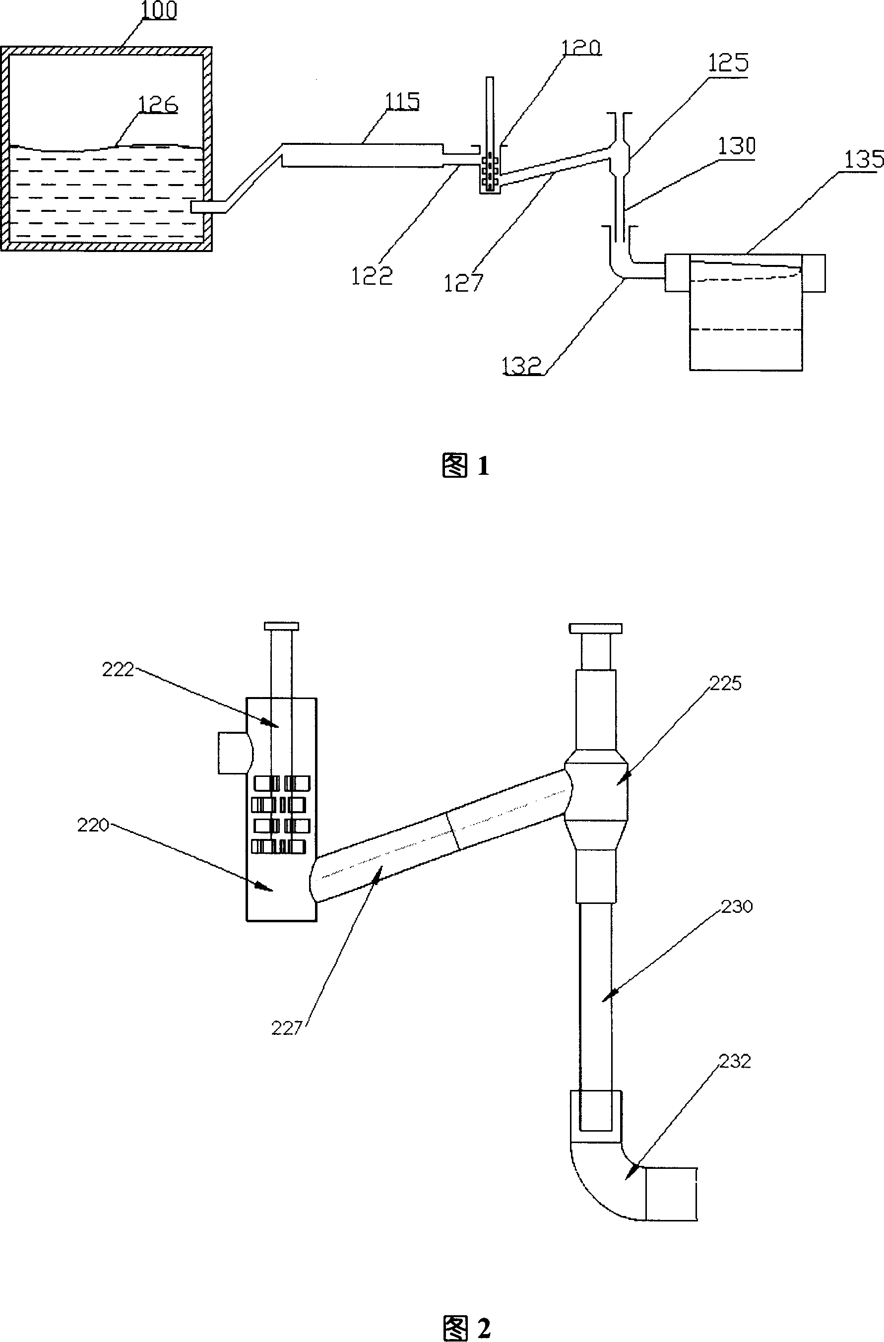
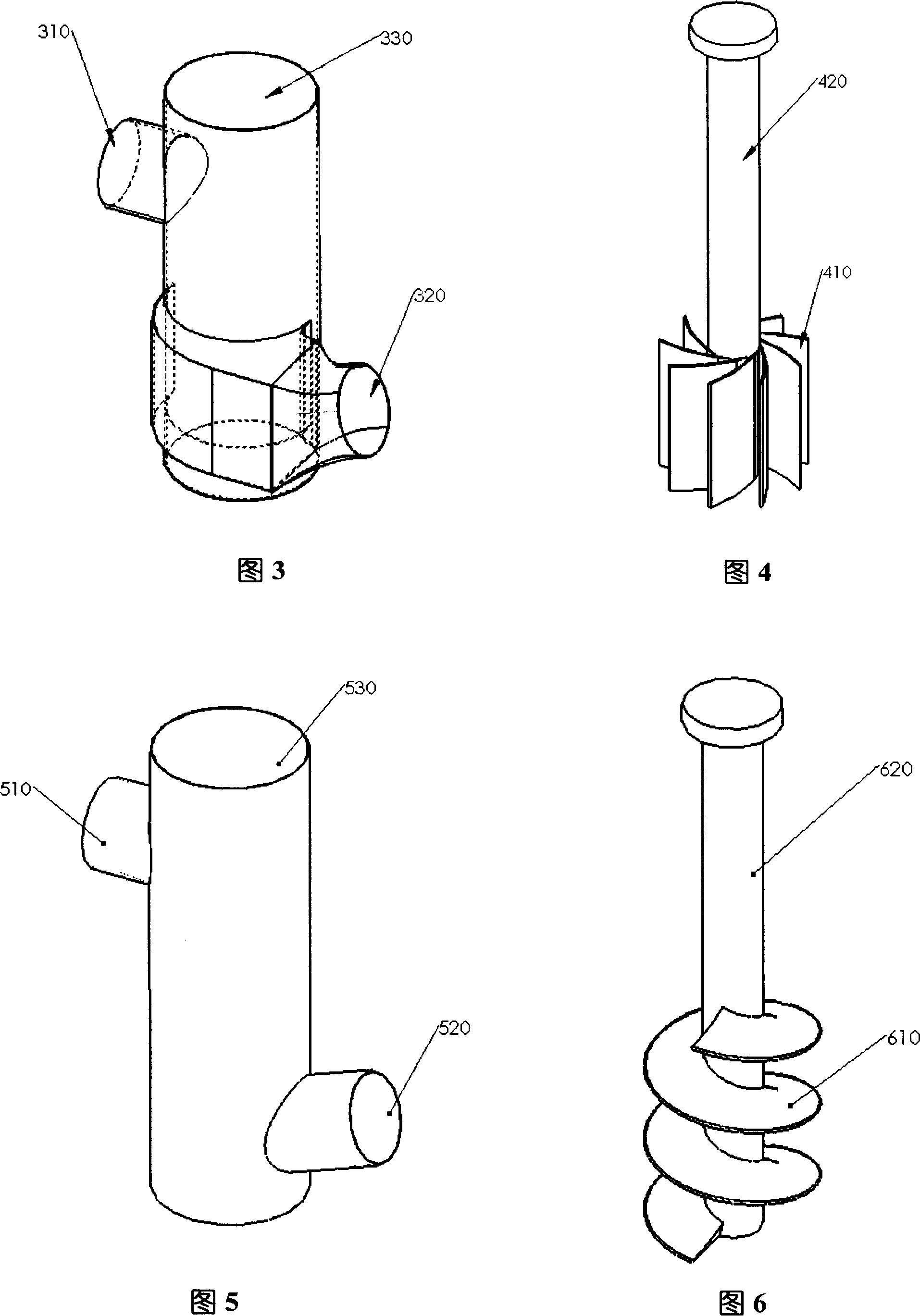
[0035] The stirred tank in the first embodiment of the present invention is centrifugal, and it has an inlet and an outlet, and the central axis of the outlet is tangent to the inner wall of the stirred tank, as shown in Figure 3 . The agitator has multiple blades, and the blades are in the shape of a turbine, as shown in Figure 4. The molten glass flows in from the inner edge of the impeller and flows out from the outer edge through the blade flow channel. Then the energy obtained by the unit weight of the fluid after being stirred by the stirrer is:

[0036] H e = QN 60 g ( 1 b 2 tan α 2 - 1 b ...

Embodiment 2

[0045] As shown in Figures 5 and 6, in another embodiment of the present invention, the stirring tank is the same as the stirring tank in the prior art, and the blades of the stirrer are helical.

[0046] Introduce the alkali-free molten glass in the patent CN200510007338.0 into the feeding system shown in the present invention, the stirring tank and the agitator in the feeding system in this embodiment are the stirring tank and the agitator shown in Figure 5 and Figure 6 respectively ; In the agitator shown in Figure 6, the outer diameter of the blade is 220mm, and the central axis shaft diameter is 70mm, and the helix angle is 15 °, and the diameter D of the pipe connecting the stirring tank and the material bowl c =150mm, length L along the cooling pipe c =2000mm, equivalent diameter of stirring tank D st =250mm, the height L of the molten glass in the stirring tank st =500mm; the diameter of the drop tube D x =220mm, glass flow length L x = 400mm. The glass viscosity ...

Embodiment 3

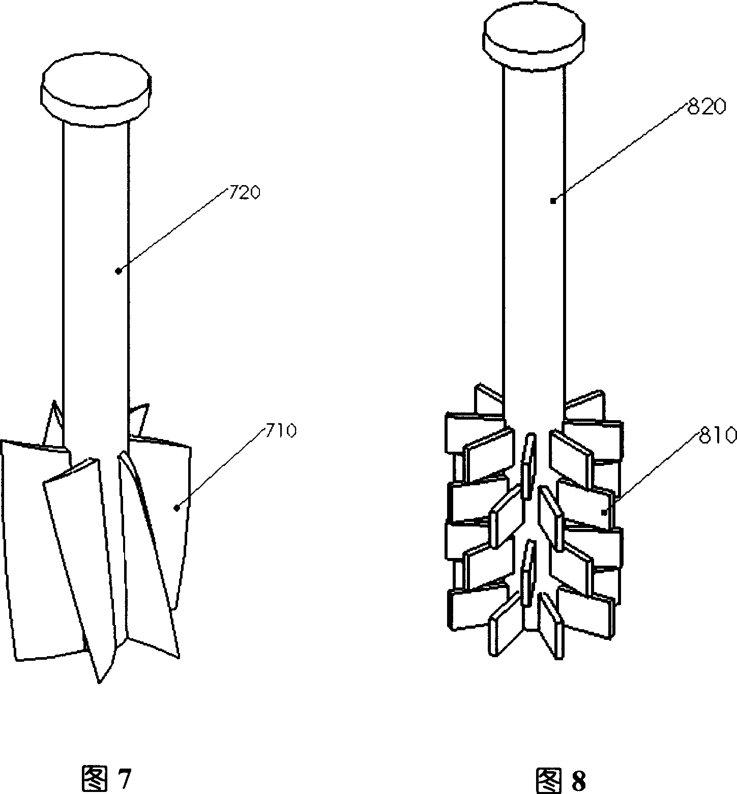
[0049] As shown in Figures 5 and 7, in the third embodiment of the present invention, the stirring tank is the same as the stirring tank of the prior art, the blades of the agitator are in multiple groups, and the blades and the central axis of the agitator have a certain angle α.

[0050] Introduce the alkali-free molten glass in the patent CN200510007338.0 into the feeding system shown in the present invention. The stirring tank and the agitator in the feeding system in the present example are the stirring tank and the agitator shown in Figure 5 and Figure 7 respectively; In the agitator shown in Figure 7, there are 6 blades, the outer diameter of the blades is 220mm, the diameter of the central shaft is 70mm, the rotation angle of the blades is 15°, and the diameter of the pipe connecting the mixing tank and the material bowl is D c =150mm, length L along the cooling pipe c =2000mm, equivalent diameter of stirring tank D st =250mm, the height L of the glass liquid in the s...


PUM


Abstract

The present invention is glass material feeding method and device for controlling glass flow rate. The present invention controls glass flow rate through changing the rotation direction and / or rotation speed of the stirrer inside the stirring bath so as to control the liquid level inside the glass bowl and control the glass flow rate inside the falling pipe. The glass material feeding device is one capable of changing the energy the glass melt obtains from the stirrer when the stirrer changes its rotation direction and / or rotation speed. The present invention has convenient glass flow rate control.

Description

technical field [0001] The present invention relates to a method and device for adjusting glass flow in glass feeding, in particular to a glass feeding method and device for controlling and adjusting glass flow in an overflow down-draw melting process, and a particularly important aspect of the present invention Applications are glass substrates used in the production of liquid crystal displays, such as substrates used in the manufacture of TFT-LCDs. Background technique [0002] Glass used in semiconductor-driven display devices, especially TFT / LCD display devices, must have very small thickness deviation and bending specifications. [0003] According to the device described in U.S. Patent No. 3338696, when the flow rate of molten glass entering the forming device changes, the thickness of the glass plate formed by the forming overflow brick in the width direction will change, which requires The flow rate of glass entering the forming unit is stabilized at a constant value...

Claims


Application Information

Patent Timeline
Patent Type & Authority Applications(China)
IPC IPC(8): C03B7/092
CPCY02P40/57
Inventor 贾伟李震兰陟万志刚
Owner HENAN ANCAI HI-TECH
Why Eureka
Try Eureka