Combustion machine and steam turbine combined circulation system for gas boiler

A gas-fired boiler and circulation system technology, which is applied in the direction of gas turbine installation, steam engine installation, combined combustion mitigation, etc., can solve the problems of unreasonable use, low net power supply efficiency, limited optional equipment, etc., and achieve the consumption ratio Large, supercharged power consumption is small, and the effect of high economy

Inactive Publication Date: 2007-06-27
中航世新燃气轮机有限责任公司
View PDF1 Cites 6 Cited by
  • Summary
  • Abstract
  • Description
  • Claims
  • Application Information

AI Technical Summary

Problems solved by technology

[0003] In the existing technology, the method of increasing the output of the gas turbine-steam turbine combined cycle power generation system using low calorific value gas fuel is to increase the power specification of the low calorific value gas turbine or to increase the auxiliary medium pressure boiler. The optional equipment is limited and the price is high; Due to the unreasonable use of medium-calorific-value fuels and low-calorific-value fuels, the net power supply efficiency of the existing combined cycle system is not very high. Therefore, it is necessary to propose a new gas turbine-steam turbine combined cycle using gas-fired boilers system

Method used


Image

  • Combustion machine and steam turbine combined circulation system for gas boiler
  • Combustion machine and steam turbine combined circulation system for gas boiler
  • Combustion machine and steam turbine combined circulation system for gas boiler

Examples


Embodiment 1

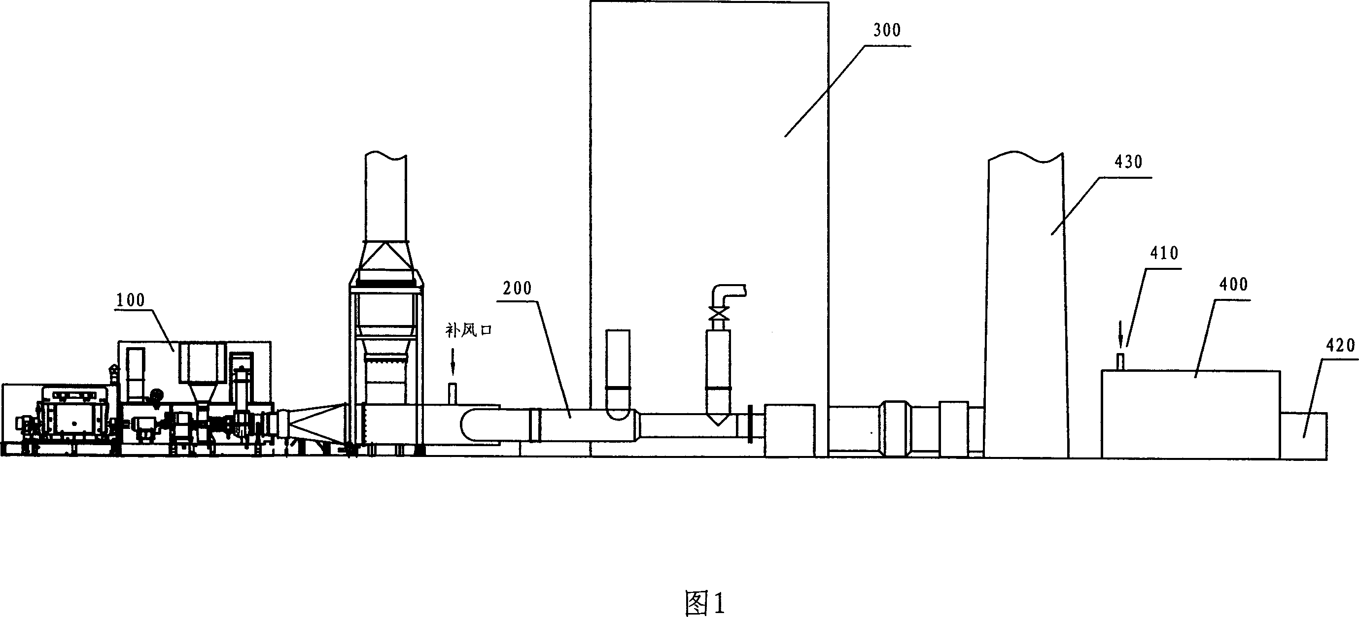
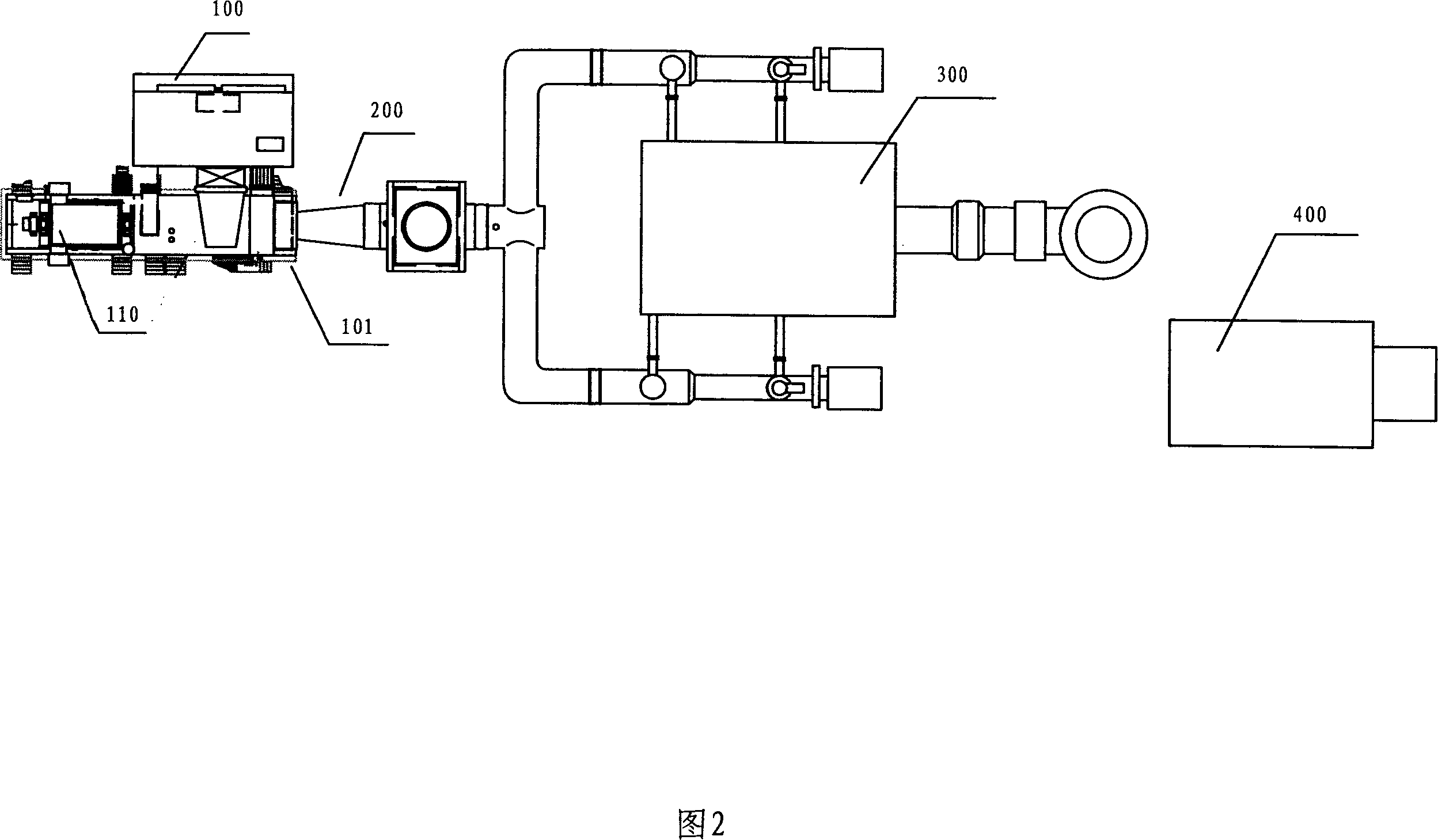
[0020] Referring to Figure 1, the gas turbine-turbine combined cycle system of the present invention includes a gas boiler, a gas turbine device, and a steam turbine device. The combustion-supporting air inlet 3083 at the lower part of the gas boiler 300 passes through a hot air duct 200 and the turbine of the gas turbine device 100 The exhaust port 101 is connected, and the turbine exhaust gas of the gas turbine device directly enters the negative pressure combustion furnace of the gas boiler as combustion-supporting air to participate in combustion. The superheated steam outlet 301 of the gas boiler is connected with the steam inlet device of the steam turbine 400. The superheated steam generated by the boiler is converted into mechanical energy in the steam turbine device; the gas boiler uses blast furnace gas as the main fuel, and the gas boiler is provided with a negative pressure combustion furnace 309, a water wall device 310, and a superheated grate 302, The combustion dev...

Embodiment 2

[0035] A gas turbine-turbine combined cycle system using a gas boiler has a gas boiler, a gas turbine device, and a steam turbine device. The combustion-supporting air inlet at the lower part of the gas boiler communicates with the turbine exhaust port of the gas turbine device through a hot air duct, The superheated steam outlet of the gas boiler is in communication with the steam turbine intake device; the gas turbine device has a calorific value of 5000~36000KJ / NM 3 The combustible gas is used as fuel; the gas boiler uses one of natural gas, blast furnace-converter mixed gas, underground gasification gas, coal gas, coal bed gas, chemical exhaust gas, and biogas as fuel. The furnace body of the gas boiler A negative pressure combustion furnace, a water wall device, a superheating grate, and a combustion device are provided, and the upper part of the gas boiler is provided with a steam drum.

[0036] In this embodiment, the structures of the gas boiler, gas turbine device, and st...


PUM


Abstract

A gas turbine and steam turbine combined circulation system using gas boiler is composed of a gas turbine unit, a steam turbine unit, and a gas boiler using blast furnace gas as main fuel and with a combustion promoting air inlet connected to the exhaust outlet of gas turbine unit and an over-heat steam outlet connected with the steam inlet of steam turbine. Said gas boiler consists of negative-pressure combustion box, water cooled wall, over-heat grate, burner and steam drum.

Description

Technical field [0001] The invention relates to a gas turbine-turbine combined cycle system using a gas boiler. The gas boiler in the system uses blast furnace gas produced by an iron-making blast furnace of a steel enterprise as fuel, which can improve the efficiency of the combined cycle system and reduce the cost of the steel enterprise. Background technique [0002] In the prior art, Chinese Patent 98116785.3 discloses an exhaust gas reheating combined cycle power generation package, which combines a boiler and a steam turbine device with a gas turbine device so that the exhaust gas from the gas turbine device is in the boiler After being heated, it is supplied as a heat source to the condenser and water supply system of the steam turbine device. It also has a cooling steam supply system that supplies steam from the low-temperature reheating system to the high-temperature part of the gas turbine and makes the gas turbine high temperature The cooling steam recovery system in w...

Claims


Application Information

Patent Timeline
Patent Type & Authority Applications(China)
IPC IPC(8): F01K23/06F02C6/18
CPCY02E20/16
Inventor 苏大为
Owner 中航世新燃气轮机有限责任公司
Why Eureka
Try Eureka