
Infrared cold/hot metal detector

A hot metal and detector technology, applied in the field of infrared cold/hot metal detectors, can solve problems such as low measurement accuracy, poor anti-interference ability, and prone to misoperation, and achieve high measurement accuracy, fast response speed, and eliminate The effect of misuse

Inactive Publication Date: 2007-06-27
上海派恩科技有限公司
View PDF0 Cites 3 Cited by
  • Summary
  • Abstract
  • Description
  • Claims
  • Application Information

AI Technical Summary

Problems solved by technology

Because the traditional infrared laser detection device simply continues to process the signal, it has the following defects: 1. Poor anti-interference ability; 2. The measurement accuracy is not high; 3. It is prone to malfunction

Method used


Image

  • Infrared cold/hot metal detector

Examples


Embodiment 1

[0020] An infrared laser detection device adopts PIC16F71 microcontroller, LM567 modem, operational amplifier adopts LM6084, semiconductor laser module adopts Sigma laser module, photosensitive receiver adopts PIN-07FSLR, output module adopts LED display output, transistor output and relay switch output .

[0021] The power supply voltage of the device is 24VDC±20%, the visible infrared laser wavelength is 650nm, the laser power is 1nw, the laser spot size is 0.1mm, and the spot deviation is 0.5mrad. position. When there is no object or the object is not in place (that is, in the standby state), the Sigma laser module continuously emits modulated laser light and is reflected back by the mirror. The photosensitive receiving tube PIN-07FSLR receives the modulated signal, filters and amplifies it, and then passes The modem LM567 demodulates and outputs a low level to the microcontroller PIC16F71. At this time, the microcontroller judges that there is no object or the object is n...


PUM


Abstract

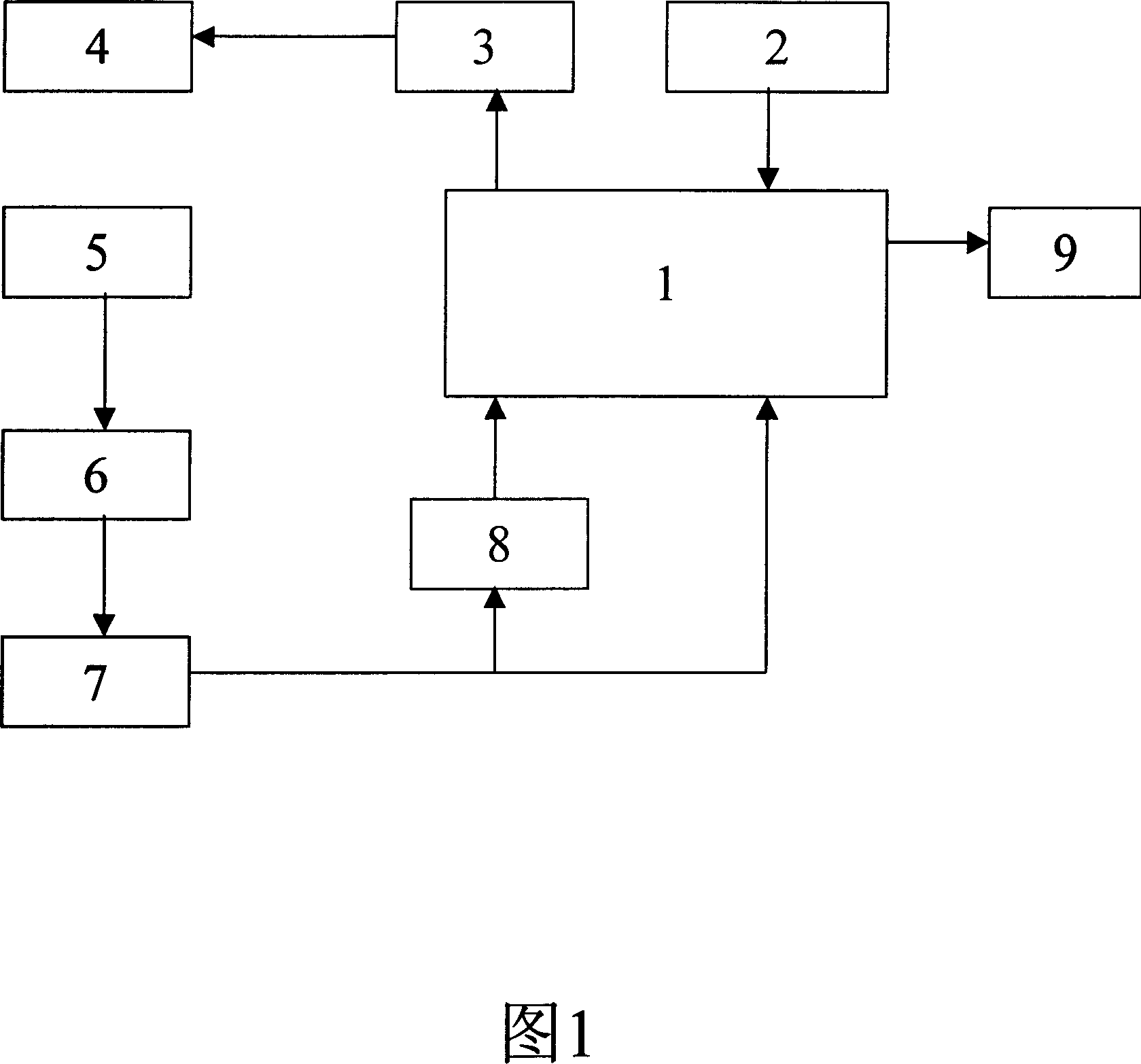
The infrared cold / hot metal detector includes microcontroller (MC), power supply module, modulation drive, semiconductor laser module (SLM), light sensitive receiver (LSR), filter, operational amplifier (OA), modem, and output module. The input end of the modulation drive is connected to the output end of MC. The output end of the modulation drive is connected to the input end of SLM. LSR is setup on laser emission optical path of SLM. The output end of LSR is connected to the input end of the filter. The output end of the filter is connected to the input end of OA. The output signal of OA is divided into two routes to output to MC: one is through modem outputted to MC; and the other is outputted to MC directly. The input end of the output module is connected to the other output end of MC. advantages are: high interference killing feature, quick response speed, and high measuring accuracy, and eliminating misoperation thoroughly.

Description

technical field [0001] The invention relates to a detection device, in particular to an infrared cold / hot metal detector. Background technique [0002] Infrared cold / hot metal detectors are widely used in the field of industrial control production lines. It is an instrument that uses visible infrared laser technology to detect the existence of objects or precisely locate objects. [0003] Infrared cold / hot metal detectors generally consist of three parts: a laser emitting module, a laser receiving and processing module, and a feedback output module. The laser transmitting module includes a laser driving circuit and a semiconductor laser module; the laser receiving module includes a photosensitive receiving tube and a signal output processing circuit; the feedback output module includes an output driving circuit and an output display circuit. The infrared cold / hot metal detector continuously emits laser signals through the laser emitting module, and judges whether the laser ...

Claims


Application Information

Patent Timeline
Patent Type & Authority Applications(China)
IPC IPC(8): G01S17/32G01S17/02
Inventor 王智李海华马性辉
Owner 上海派恩科技有限公司
Learn More