Hollow power transmission shaft and method of manufacturing the same

A technology of a power transmission shaft and a manufacturing method, which is applied in the field of hollow power transmission shafts, can solve the problems of increasing the number of parts, decreasing the strength of the opposite side material, and increasing the manufacturing cost, and achieves a small number of parts and suppresses the increase in tooth thickness. The effect of large, closed work is easy

Active Publication Date: 2007-06-27
NTN CORP
View PDF8 Cites 14 Cited by
  • Summary
  • Abstract
  • Description
  • Claims
  • Application Information

AI Technical Summary

Problems solved by technology

If such a spline with a greatly increased O.P.D. of the end portion is fitted into a spline hole of an opposite side member such as the inner ring of a constant velocity free joint, the portion with an increased O.P.D. The spline part of the spline hole is partially separated, and there is a possibility that the strength of the material on the opposite side will decrease
[0022] Furthermore, when spline-fitting the shaft and the opposite side member, in order to suppress the looseness (gap) of the fitting part, the shaft may be given a helix angle, but the O.P.D. , it is difficult to optimally set the helix angle
[0023] In addition, the rubber closure pin of Patent Document 7 requires a relatively large force to press into the hollow part, so there is a problem that assembly work takes time.
[0024] Since the elastic locking pin of Patent Document 8 is combined with a stopper made of a shape memory alloy, the assembly work can be simplified, but the number of parts increases.
[0025] In addition, since all the deadbolts are product shapes molded into desired shapes and sizes, there is also a problem of high production costs.

Method used


Image

  • Hollow power transmission shaft and method of manufacturing the same
  • Hollow power transmission shaft and method of manufacturing the same
  • Hollow power transmission shaft and method of manufacturing the same

Examples


Embodiment Construction

[0082] Embodiments of the present invention will be described below with reference to the drawings.

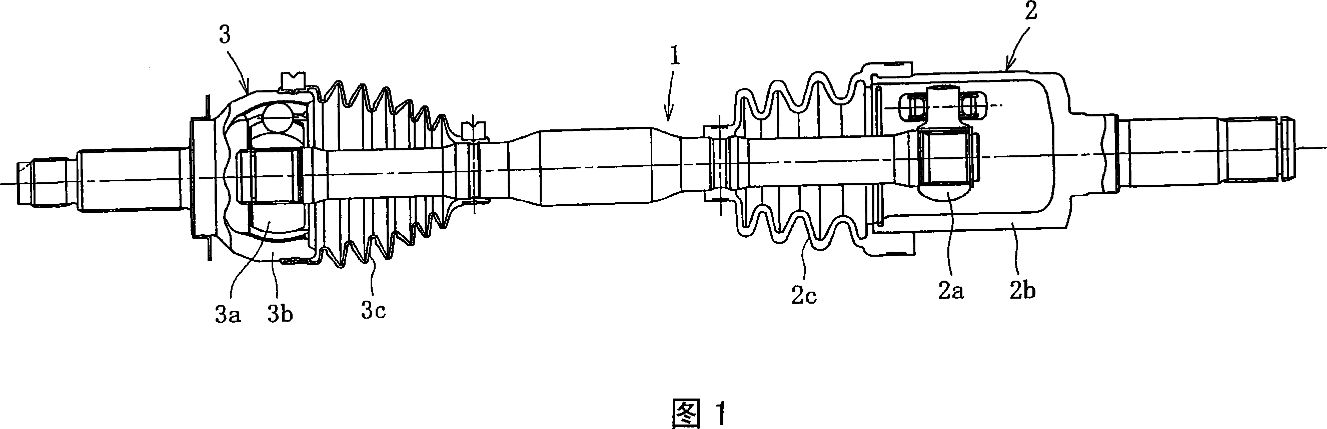
[0083] What Fig. 1 shows is a power transmission mechanism of an automobile, which has: a hollow power transmission shaft 1, a sliding type constant velocity free joint 2 connected to one end of the power transmission shaft 1, and another shaft connected to the power transmission shaft 1. Fixed type constant velocity free joint 3 at one end. In the power transmission mechanism of this embodiment, the sliding type constant velocity free joint 2 is connected to the reduction gear (differential device), and the fixed type constant velocity free joint 3 is connected to the drive wheel side. One end of the power transmission shaft 1 is spline-connected to the tripod member 2a of the sliding type constant velocity free joint 2, and boots 2c are respectively fixed to the outer circumference of the end portion of the outer ring 2b of the sliding type constant velocity free joint 2. a...


PUM


Abstract

The invention provides a method of manufacturing a hollow power transmission shaft capable of securing stable quality even if a difference in wall thickness and a difference in hardening rate are present in the axial direction of the transmission shaft. A movable induction heating coil (5) is wrapped around the outer peripheral surface (1g) of a hollow shaft raw material (1'), and moved in the axial direction while flowing a high-frequency current with a specified frequency to the induction heating coil (5) to induction-harden the shaft raw material from the outer peripheral surface (1g). In this case, for small diameter parts (1b) with a rather large wall thickness, the frequency of the high-frequency current led to the induction heating coil (5) is relatively reduced, and for a large diameter part (1a) with a rather small wall thickness, the frequency of the high-frequency current led to the induction heating coil (5) is relatively increased.

Description

technical field [0001] The present invention relates to a hollow power transmission shaft connected to a joint such as a constant velocity free joint and a manufacturing method thereof. The hollow power transmission shaft of the present invention can be applied to devices such as a drive shaft (drive shaft) and a propulsion shaft (propulsion shaft) constituting a power transmission system of an automobile. Background technique [0002] For example, in a power transmission system of an automobile, a power transmission shaft that transmits power from a reduction gear (differential gear) to drive wheels is called a drive shaft (drive shaft). Especially in the drive shaft used for FF vehicles, since a large operating angle and constant velocity are required when the front wheel is steered, and the function of absorbing displacement in the axial direction is required in relation to the suspension device, it is often used The structure is that one end of the sliding type constant...

Claims


Application Information

Patent Timeline
Patent Type & Authority Applications(China)
IPC IPC(8): F16C3/02
Inventor 樱井胜弘中川亮新保正道山口昌巳平冈恒哲
Owner NTN CORP
Why Eureka
Try Eureka