Composite rectifying device for current generating system of deep water basin

A technology of deep water test and rectification device, which is applied in the field of ships and ocean engineering, can solve problems such as undiscovered, and achieve the effect of easy realization, simple structure and shortened distance

Active Publication Date: 2007-07-11
SHANGHAI JIAO TONG UNIV
View PDF0 Cites 7 Cited by
  • Summary
  • Abstract
  • Description
  • Claims
  • Application Information

AI Technical Summary

Problems solved by technology

In a further search, no good device was found to rectify the ocean current simulated by the deep pool

Method used


Image

  • Composite rectifying device for current generating system of deep water basin

Examples


Embodiment Construction

[0018] The technical solution of the present invention will be further described below in conjunction with the accompanying drawings.

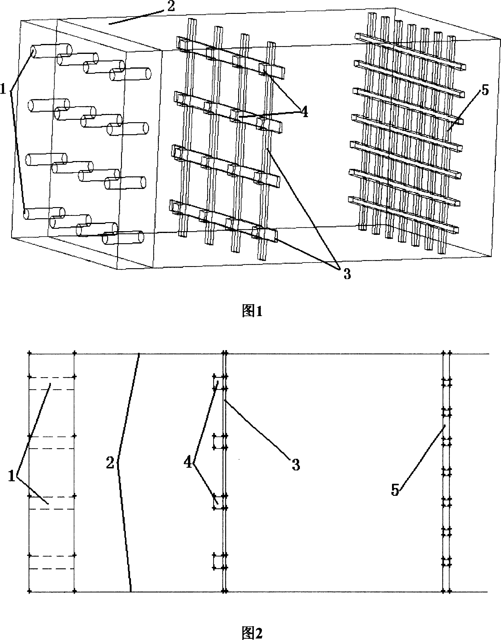
[0019] The structural layout of the compound rectification device of the flow-making system of the deep-water test pool of the present invention is shown in Figure 1. A rectifying plate is installed at a distance between 0.1m and 0.4m from the exit of the flow-making nozzle 1, and the rectifying plate is supported by The frame 3 and the rectification block 4 constitute. The supporting frame 3 is constructed into a grid shape by criss-crossing slender slats, and its outer ends are fixed on the walls 2 around the pool. A rectifying block 4 is installed at each cross point where the supporting frames 3 intersect, and the rectifying block 4 corresponds to each nozzle on the flow-making nozzle 1 respectively. The size of the rectifying block 4 corresponds to the size of the aperture of the flow-making nozzle 1 .

[0020] The shape of the rectifyi...


PUM


Abstract

The invention relates to a deep water experimental tank hybrid rectifier. Close to the system nozzle output, the rectifying plate is installed made of support frame and rectifying block, the support frame being built into intersected grid with high rigidity and thin long plates, the outside fastened to the surrounding walls of the water pool, each crossing point of the support frame having a rectifier block that corresponding to each nozzle, with the size of the rectifying block matching with the diameter of the nozzle hole. When the current ejected out and bumped into the rectifying block, it can reach even and stable status, with the analog water flow more like real ocean current, improving the testing effect. The even finer rectifying net at the rear side of the rectifying plate can further improve the rectifying effect.

Description

technical field [0001] The present invention relates to a water flow rectification device, in particular to a composite rectification device for a flow-making system of a deep-water test pool, which rectifies the ocean current simulated by the flow-making system of an ocean deep-water test pool, so that it can reach the space and time as soon as possible. stable and uniform state. The invention is mainly used in the fields of ships and ocean engineering. Background technique [0002] With the development of offshore oil and gas development activities from offshore to deep sea, many newly developed offshore oil production and processing devices suitable for deep sea development are also emerging, including Compliant Platform (CT), Floating Production Storage Unit (FPSO), Tension Leg Platform (TLP), large deepwater multifunctional semi-submersible platform (Semi-FPS), single column platform (SPAR), floating production drilling and storage unit (FPDSO), etc. Due to the harsh ...

Claims


Application Information

Patent Timeline
Patent Type & Authority Applications(China)
IPC IPC(8): G01M10/00
Inventor 杨建民陈刚彭涛汪学锋毛丞弘吕海宁
Owner SHANGHAI JIAO TONG UNIV
Why Eureka
Try Eureka