

A making method for fully automated small ultra-thin chip inductor
An ultra-thin patch type, manufacturing method technology, applied in the direction of inductor/transformer/magnet manufacturing, inductors, fixed inductors, etc., can solve the problems of low production efficiency, product damage, copper wire coil damage, etc., to achieve production man-hours Less, more versatile, and the effect of avoiding damage
- Summary
- Abstract
- Description
- Claims
- Application Information
AI Technical Summary
Problems solved by technology
Method used
Image

Examples
Embodiment Construction
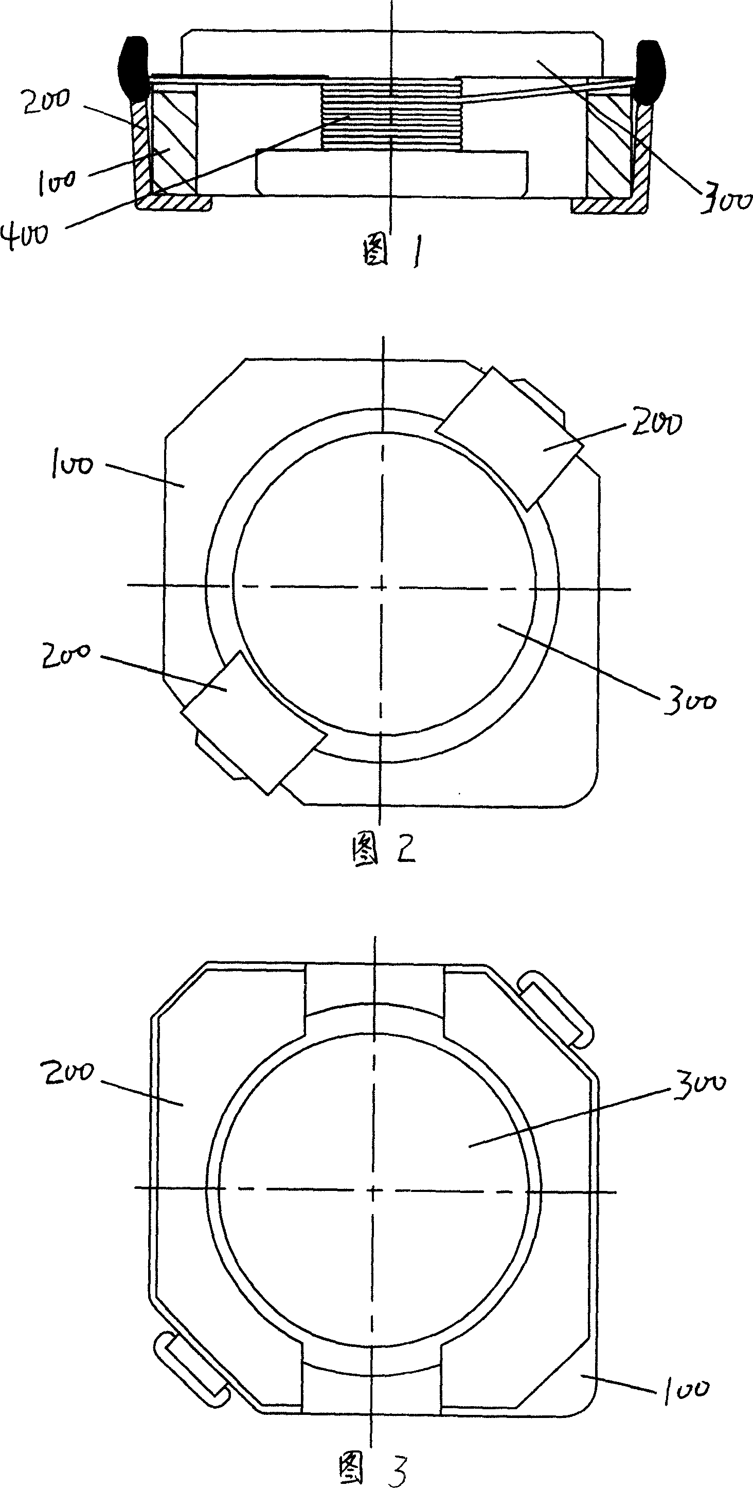
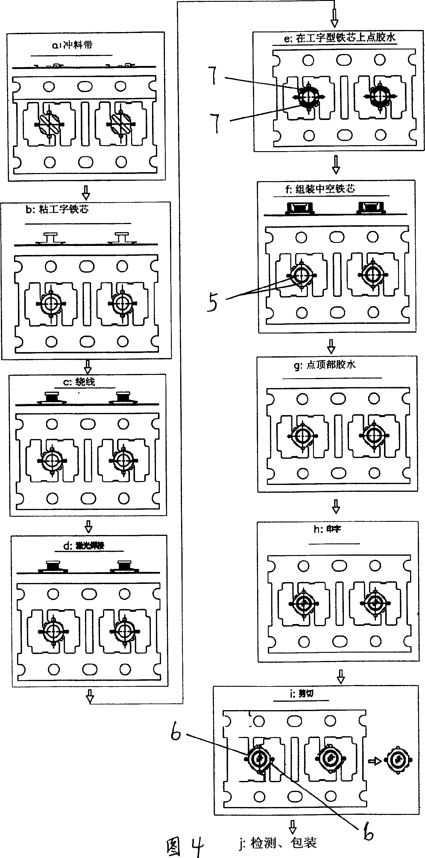
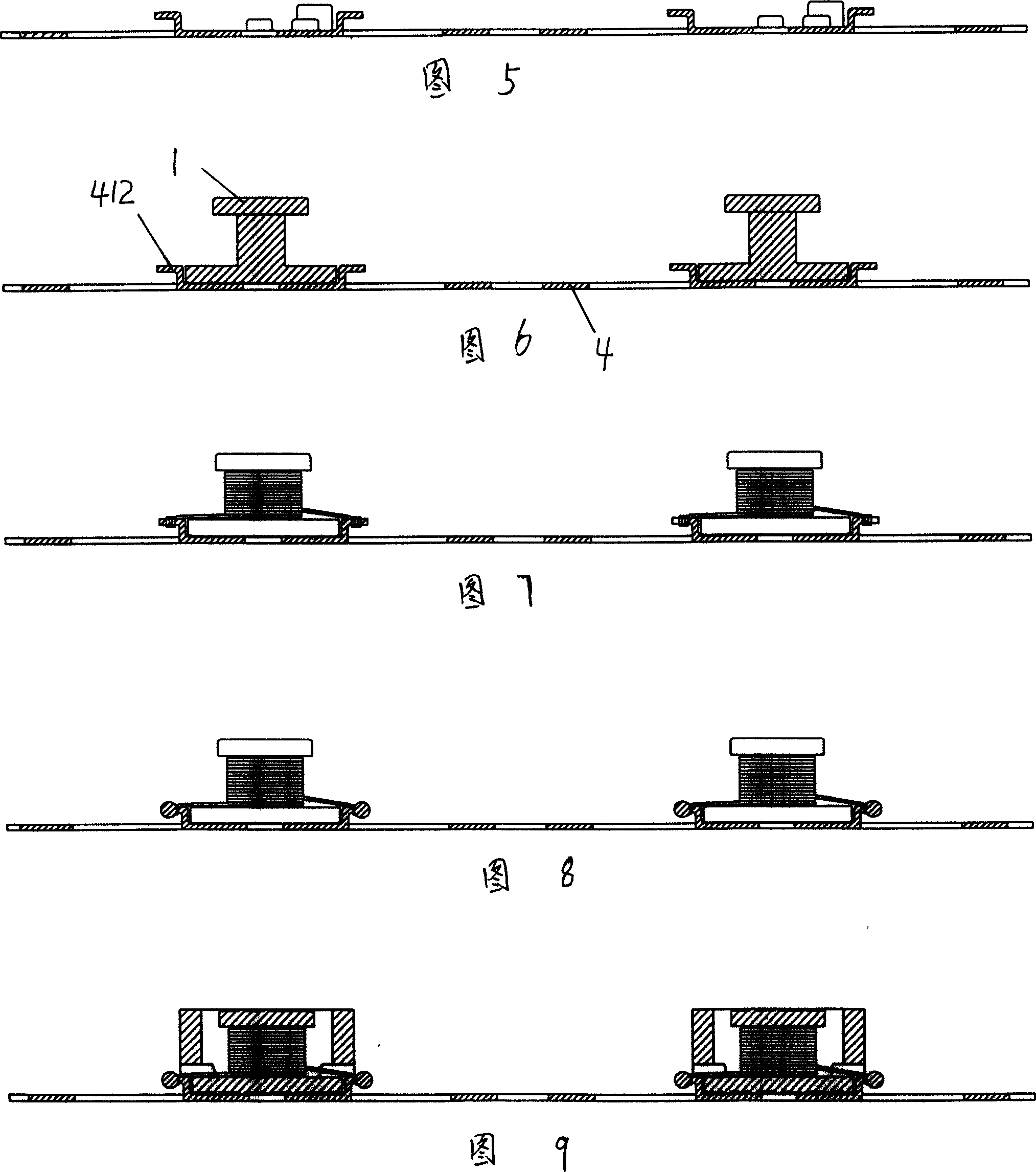
[0043] A kind of manufacture method of full-automatic small-sized ultra-thin patch type inductance, it is main raw material with I-shaped iron core 1, hollow iron core 2, copper coil 3, copper strip 4, and it comprises following process steps (as shown in Figure 4 shown):
[0044] a), punch a plurality of neatly arranged inductance bases 41 on the main body 4 of the copper strip, the base 41 is connected to the main body 4 of the strip through two 180-degree symmetrical connection sides 42, and there is a gap between the two connection sides 42 The inductance base 41 is divided into a separation hole 43 of two welding plates 411, the length of the separation hole 43 is slightly larger than the size of the hollow iron core 2; each welding plate 411 is respectively provided with an upwardly bent winding wire The terminal 412 and the small boss 413 protruding outwards are also punched with a positioning hole 44 for pulling to the main body of the material strip for the following ...
PUM
 Abstract
Description
Claims
Application Information