The high-frequency circuit structure for the mutual conversion of the coaxial electric mode of the rectangular waveguide mode and round waveguide

A rectangular waveguide and high-frequency circuit technology, applied in circuits, waveguide-type devices, electrical components, etc., can solve the problem that the gyrotron is not well solved, and achieve the effects of simple structure, small mode distortion, and improved work efficiency.

Inactive Publication Date: 2007-07-11
INST OF ELECTRONICS CHINESE ACAD OF SCI
View PDF0 Cites 12 Cited by
  • Summary
  • Abstract
  • Description
  • Claims
  • Application Information

AI Technical Summary

Problems solved by technology

At present, this problem has not been well

Method used


Image

  • The high-frequency circuit structure for the mutual conversion of the coaxial electric mode of the rectangular waveguide mode and round waveguide

Examples


Embodiment Construction

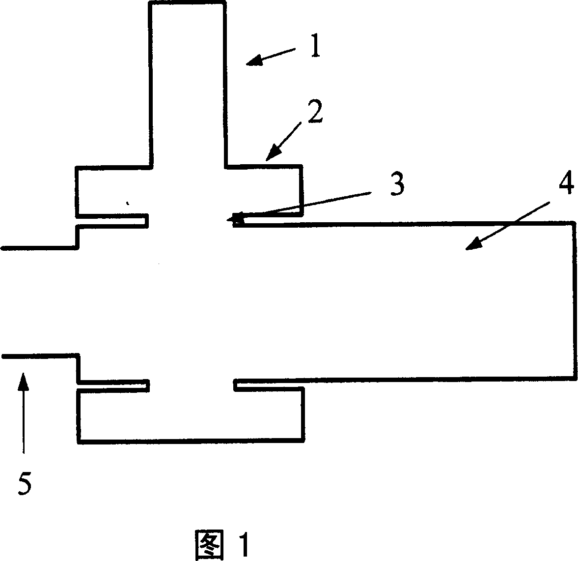
[0009] The high-frequency circuit structure of the present invention adopts the rectangular waveguide side input cylindrical resonant cavity, and utilizes the rectangular waveguide TE 10 The mode excites the TE of the coaxial resonator n1 mode, the electromagnetic field energy excites the circular electric mode TE in the circular waveguide through the periodically arranged coupling holes 0n mold.

[0010] As shown in FIG. 1 , the rectangular waveguide 1 and the circular waveguide 4 are connected orthogonally, and their central axes are perpendicular to each other. At the junction of the rectangular waveguide 1 and the circular waveguide 4, the sides are respectively connected to the inner and outer walls of the coaxial resonant cavity 2, the coaxial resonant cavity 2 is connected to the circular waveguide 4 through the coupling hole 3, and one end of the circular waveguide 4 is connected to the working mode TE 0n Circular waveguide 5 with mode cut-off; coupling hole 3 is loc...


PUM


Abstract

This invention relates to one rectangle wave guide mode and round wave guide mode conversion high frequency circuit structure, wherein, its rectangle wave guide and co-axis resonance chamber is connected by cross; the co-axis resonance chamber inner wall is connected to the round wave guide through the couple holes with other end connected to the round wave guide for work mode of TE0n; the rectangle wave guide mode TE10 mode excitation co-axis resonance chamber mode.

Description

technical field [0001] The invention relates to the technical field of a gyrotron traveling wave amplifier and a gyrotron return wave tube of a high-power broadband millimeter-wave device, and is a novel high-frequency circuit structure for mutual conversion between a rectangular waveguide mode and a circular waveguide circular electric mode. Background technique [0002] The gyrotron is a millimeter-wave and quasi-millimeter-wave high-power coherent radiation source based on the electron cyclotron maser (ECM) mechanism. Energy microwave weapons and other aspects have great application value, and the international community attaches great importance to its theoretical and experimental research. For the cyclotron TWT, its broadband amplification characteristics require a broadband input coupling circuit to cooperate; for the broadband continuous tuning cyclotron return wave tube, its high-frequency field energy needs to be fed to the load through a broadband output coupling c...

Claims


Application Information

Patent Timeline
IPC IPC(8): H01P5/08
Inventor 刘本田张燕生
Owner INST OF ELECTRONICS CHINESE ACAD OF SCI
Why Eureka
Try Eureka