
A soft switch reversion conversion circuit for the resonance DC step

A resonant DC and inverter circuit technology, applied in the direction of converting AC power input to DC power output, electrical components, high-efficiency power electronics conversion, etc., can solve the problems of low power density and difficulties of inverters, and overcome the reverse Recovery problems, simple methods, and easy engineering effects

Inactive Publication Date: 2007-07-11
NORTHWESTERN POLYTECHNICAL UNIV
View PDF0 Cites 13 Cited by
  • Summary
  • Abstract
  • Description
  • Claims
  • Application Information

AI Technical Summary

Problems solved by technology

[0005] In order to overcome the disadvantages of the prior art, such as the difficulty in forming the zero-voltage groove of the bus bar and the low power density of the inverter, the present invention provides a circuit for realizing the soft switching operation of the power device of the inverter bridge, so as to improve the working efficiency and power density of the inverter. Reduce electromagnetic interference, simplify control methods, and facilitate engineering implementation

Method used


Image

  • A soft switch reversion conversion circuit for the resonance DC step
  • A soft switch reversion conversion circuit for the resonance DC step
  • A soft switch reversion conversion circuit for the resonance DC step

Examples


Embodiment 1

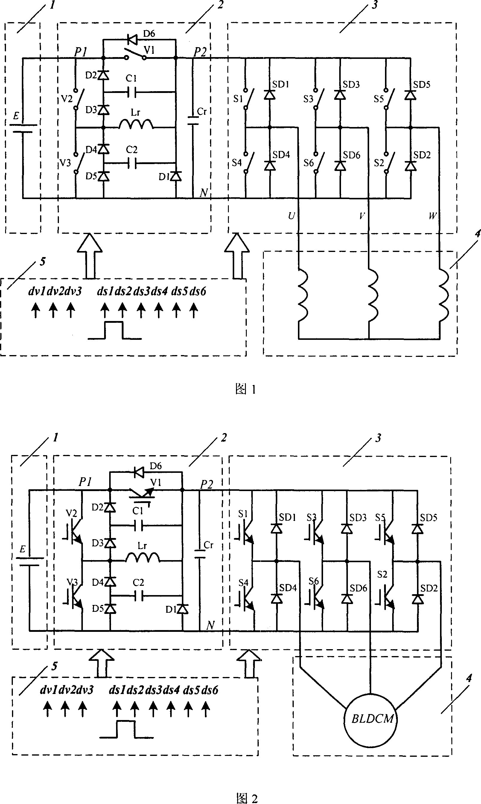
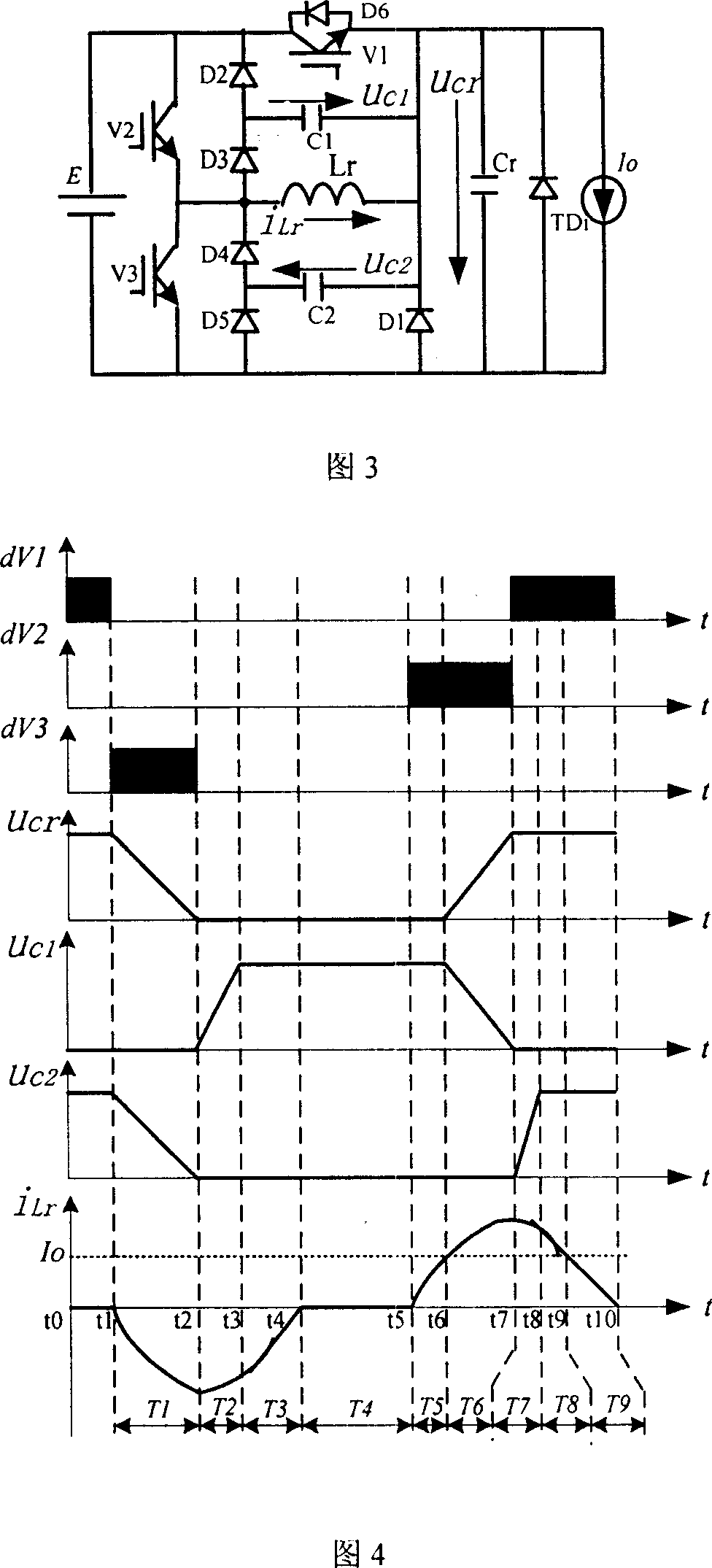
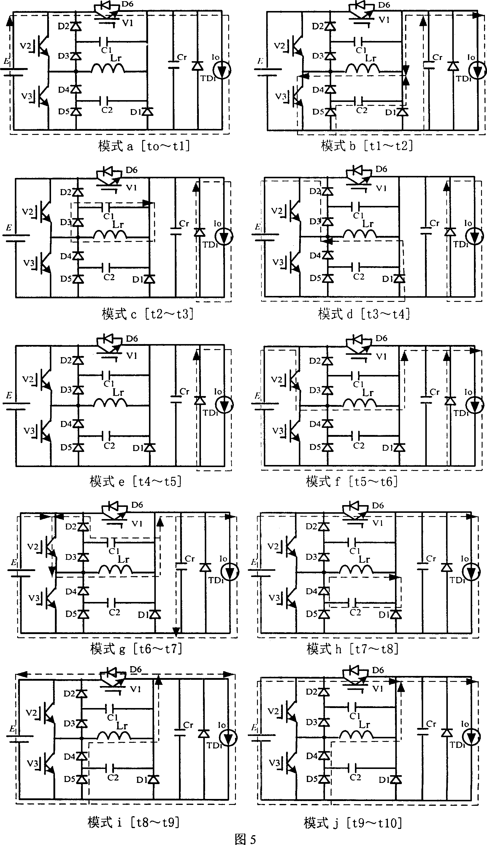
[0035] According to Embodiment 1 of the present invention, as shown in Figure 1, a new resonant DC link soft-switching three-phase inverter main circuit is provided, which can be used for three-phase asynchronous motors, three-phase brushless DC motors, and three-phase synchronous motors drive etc. The invention includes: a DC power supply 1, a resonant auxiliary circuit 2, a known three-phase inverter bridge 3, an inductive load 4, and a control circuit 5. In order to illustrate the working principle of the auxiliary circuit of the present invention, Fig. 1 can be replaced by equivalent circuit Fig. 3, because the inductance of the load is much greater than the resonant inductance, the load current at the transition moment of the inverter switch state can be considered as the constant current source Io, and the inverter bridge switch At the moment of state transition, the freewheeling diode is equivalent to TDi. Assuming that the inverter bridge switch needs switching action...

Embodiment 2

[0058] According to the second embodiment of the principle of the present invention, as shown in FIG. 2 , a new resonant DC link soft-switching inverter circuit is provided, which is used for driving a three-phase permanent magnet brushless DC motor. The present invention includes: a DC power supply 1 , a resonant auxiliary circuit 2 of the present invention, a known three-phase inverter bridge 3 , a brushless DC motor 4 and a control circuit 5 . In the second embodiment, on the basis of the first embodiment, the inductive load is replaced with a specific brushless DC motor, and the working principle is the same as that of the first embodiment, which will not be repeated here. Here, simulations and experiments are mainly carried out on the present invention. During the simulation, the same operating parameters as those in the experiment were selected. The brushless DC motor 4 works in the known star six state, and its parameters are: rated power 40W, rated voltage 24V, number ...


PUM


Abstract

This invention discloses one resonance direct flow flexible inverter circuit, which comprises one direct current power, one control circuit, one inverter bridge and drive load, wherein, the direct current power and inverter bridge are added with aid resonance circuit composed of three aid switches, six diodes, three capacitors and one inductance; when the power parts converts from status to another one, the control circuit sends control signal for reasonable aid switch V1, V2 and V3.

Description

technical field [0001] The invention relates to a switch conversion circuit, in particular to a switch inverter circuit for a bridge inverter. Background technique [0002] At present, most bridge inverters at home and abroad adopt hard-switching pulse width modulation (PWM) technology. In PWM inverters, the output transformer, AC filter inductor and radiator account for the main part. In order to reduce the inverter To increase the power density of the inverter, the volume and weight of the inverter must be increased, and the switching frequency of the inverter must be increased. However, after the high frequency of the power device, the switching loss increases sharply, resulting in a sharp rise in the junction temperature of the power device, which prevents the high frequency of the power conversion circuit; and the large voltage and current change rate of the power device after the high frequency Generate large electromagnetic interference (EMI), affecting the normal o...

Claims


Application Information

Patent Timeline
Patent Type & Authority Applications(China)
IPC IPC(8): H02M7/5387
CPCY02B70/1441Y02B70/1491Y02B70/10
Inventor 贺虎成刘卫国马瑞卿李榕
Owner NORTHWESTERN POLYTECHNICAL UNIV
Learn More