Supercharge Your Innovation With Domain-Expert AI Agents!

Expanded beam connector with discrete alignment assembly

a technology of optical connectors and alignment assemblies, applied in the field of optical connectors, can solve the problems of difficult physical contact between the fiber and the light path of the mating connector, profoundly detrimental effect on the optical transmission, and the inability to precisely machine the inserts, etc., to facilitate the critical alignment of the lens and the fiber, and facilitate the manufacturing process. the effect of simple structur

Inactive Publication Date: 2018-07-31
TE CONNECTIVITY CORP
View PDF20 Cites 1 Cited by
  • Summary
  • Abstract
  • Description
  • Claims
  • Application Information

AI Technical Summary

Benefits of technology

The present invention provides an alignment assembly for optical components that is separate from the insert. This allows for easier and more cost-effective manufacturing. The alignment is achieved through a cylindrical resilient sleeve that provides a centering clamping force, eliminating the need for precise tolerances in the insert. The use of an easily-handled ferrule stub or a ferrule of the cable assembly reduces costs and complexity. The alignment assembly is simple to inspect and handle, improving the likelihood of successful connections. The use of A / R coating allows for the use of less expensive components and enables the same connector to be used for different applications. Overall, the alignment assembly simplifies the manufacturing process and improves the likelihood of successful connections.

Problems solved by technology

Such connectors are used traditionally in high vibration and / or dirty environments, where “physical contact” between the fiber and the light path of mating connector is problematic.
Specifically, in dirty environments, particulates may become trapped between connectors during mating.
Such debris has a profoundly detrimental effect on the optical transmission since the particles are relatively large compared to the optical path (e.g., 10 microns diameter in single mode) and are therefore likely to block at least a portion of the optical transmission.
Furthermore, in high-vibration environments, optical connectors having ferrules in physical contact tend to experience scratching at their interface.
This scratching diminishes the finish of the fiber end face, thereby increasing reflective loss and scattering.
Not only is machining such a curved seat challenging, but also verifying its tolerance compliance is error prone.
Thus, the existing verification process tends to be unreliable such that the tolerance compliance of the assembly is not known with any real certainty until the final optical measurement is performed on the product.
Determining noncompliance at this stage of manufacture is inefficient and wasteful.
Additionally, during insertion of the cable assembly into the cavity, often the ferrule scrapes along the sidewall of the insert's borehole, creating shavings or debris.
This debris may settle on the ferrule end face in a way that can degrade the signal and the return loss.
Due to the presence of machining tolerances and the difficulty of verification, it is often required that tuning is applied in order to align the fiber axis of the cable assembly with the axis of the lens.

Method used


Image

  • Expanded beam connector with discrete alignment assembly
  • Expanded beam connector with discrete alignment assembly
  • Expanded beam connector with discrete alignment assembly

Examples


Embodiment Construction

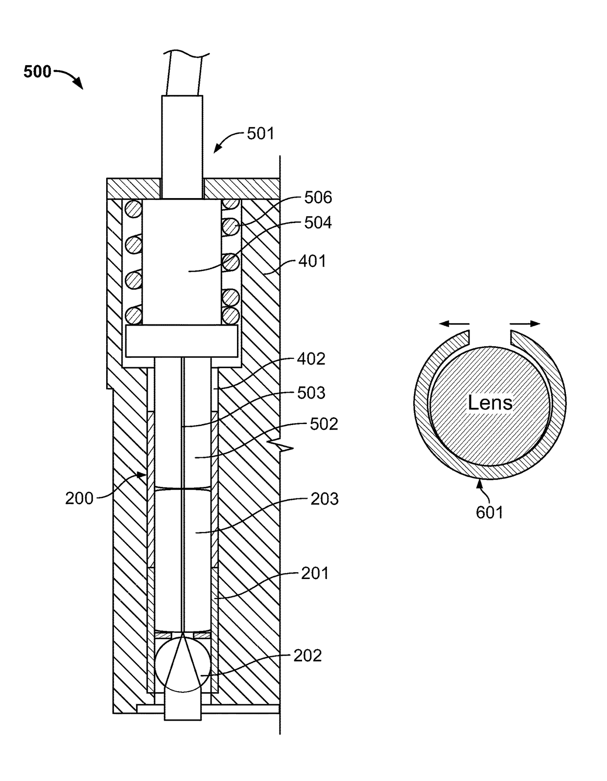
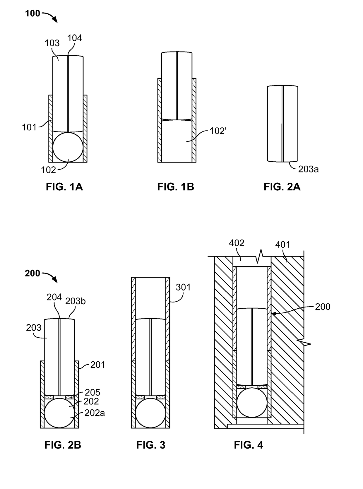
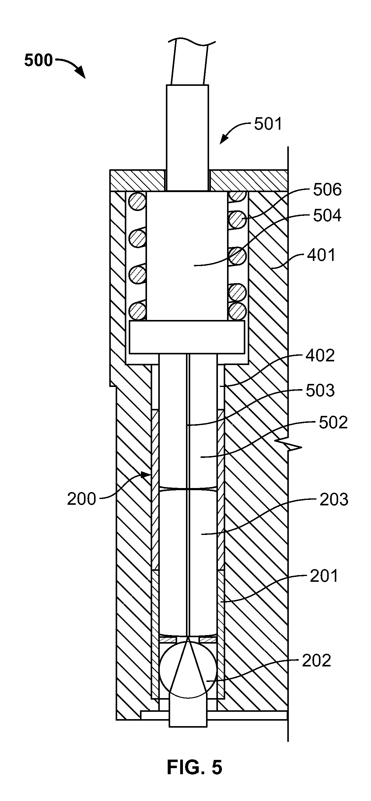
[0030]Referring to FIGS. 1(a)&1(b) and FIGS. 10(a) and (b) embodiments are shown of an alignment assembly 100, 1000 for insertion into an insert of an expanded beam connector. As used herein the term “connector” refers to any device used to join a segment of the conductor to (1) another conductor segment, (2) an active device such as a photonic radiation source, detector, or repeater, and (3) a passive device, such as switch, multiplexer, or attenuator. A typical optical fiber connector comprises housing and a cable assembly within the housing. The cable assembly comprises a ferrule, which has one or more bore holes to accommodate fibers, and a fiber secured in each bore hole such that the end of the fiber is presented for optical coupling by the ferrule. The housing is designed to engage a “mating structure” having an optical path to which the fiber optically couples during mating. The mating structure may be another connector or an active or passive device as mentioned above. The ...


PUM


Abstract

An alignment assembly for disposition in an insert for an expanded beam connector, said alignment assembly comprising: (a) at least one cylindrical sleeve having an inner first diameter, and an outer diameter configured to be received in said insert of said connector; (b) a lens disposed in said sleeve, and having a round periphery with a second diameter larger than said first diameter; and (c) wherein said sleeve is configured to at least partially accept a ferrule having a round periphery with a third diameter essentially the same as the second diameter, said ferrule comprising a fiber for optically coupling with said lens.

Description

CROSS-REFERENCE TO RELATED APPLICATION[0001]This application is a continuation in part of U.S. patent application Ser. No. 14 / 832,741, filed Aug. 21, 2015, hereby incorporated by reference.FIELD OF DISCLOSURE[0002]The present invention relates generally to an optical connector, and, more specifically, to an expanded beam optical connector.BACKGROUND[0003]Optical fiber connectors are a critical part of essentially all optical fiber communication systems. For instance, such connectors are used to join segments of fiber into longer lengths, to connect fiber to active devices, such as radiation sources, detectors and repeaters, and to connect fiber to passive devices, such as switches, multiplexers, and attenuators. The principal function of an optical fiber connector is to hold the fiber end such that the fiber's core is axially aligned with an optical pathway of the mating structure. This way, light from the fiber is optically coupled to the optical pathway.[0004]Of particular interes...

Claims


Application Information

Patent Timeline
Patent Type & Authority Patents(United States)
IPC IPC(8): G02B6/38G02B6/32
CPCG02B6/3877G02B6/3874G02B6/3846G02B6/32G02B6/423
Inventor GRINDERSLEV, SOREN
Owner TE CONNECTIVITY CORP
Features
  • R&D
  • Intellectual Property
  • Life Sciences
  • Materials
  • Tech Scout
  • Unparalleled Data Quality
  • Higher Quality Content
  • 60% Fewer Hallucinations
Learn More