Power storage device

a power storage device and power technology, applied in secondary cells, non-aqueous electrolyte cells, cell components, etc., can solve the problems of deterioration of the charge-discharge characteristics of the power storage device, and achieve excellent charge-discharge cycle characteristics, high output power, and high capacity

Active Publication Date: 2018-08-14
PANASONIC INTELLECTUAL PROPERTY MANAGEMENT CO LTD
View PDF21 Cites 0 Cited by
  • Summary
  • Abstract
  • Description
  • Claims
  • Application Information

AI Technical Summary

Benefits of technology

[0022]According to the present invention, it is possible to provide a power storage device having a high capacity and a high output power and being excellent in charge-discharge cycle characteristics.

Problems solved by technology

Specifically, when the organic compound is crystalline during both charging and discharging, the charge-discharge characteristics are good; and when the organic compound is not crystalline during at least one of charging and discharging, the charge-discharge characteristics of the power storage device are deteriorated.

Method used


Image

  • Power storage device
  • Power storage device
  • Power storage device

Examples


example 1

[0195]The same coin battery as shown in FIG. 10 was fabricated as the power storage device of the present invention in the following procedures.

(1) Formation of Positive Electrode

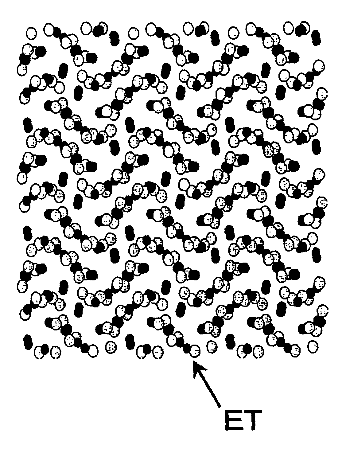
[0196]For the positive electrode active material, bis(ethylenedithio)tetrathiafulvalene (available from Tokyo Chemical Industry Co., Ltd.) was used as the organic compound having a conjugated π-electron cloud. The positive electrode active material had been purified and recrystallized beforehand. The purification and recrystallization of the positive electrode active material was performed by dissolving 50 mg of the positive electrode active material in 20 ml of carbon disulfide serving as the solvent, adding 20 ml of hexane thereto, and allowing the resultant solution to stand in an environment at a temperature of 5° C. to cause reprecipitation.

[0197]30 mg of the positive electrode active material (powder of approximately 5 μm in average particle size) and 30 mg of acetylene black (powder of 35 μm in avera...

example 2

[0201]As the electrolyte, a mixed solvent of propylene carbonate and diethyl carbonate (volume ratio 1:5) containing 0.5 mol / L lithium hexafluorophosphate was used. Except for this, Battery B was fabricated and charged and discharged in the same manner as in Example 1.

example 3

[0202]As the electrolyte, a mixed solvent of propylene carbonate and diethyl carbonate (volume ratio 1:5) containing 0.5 mol / L lithium perchlorate was used. Except for this, Battery C was fabricated and charged and discharged in the same manner as in Example 1.


PUM

PropertyMeasurementUnit
relative dielectric constantaaaaaaaaaa
dielectric constantaaaaaaaaaa

Abstract

A power storage device of the present invention includes a positive electrode, a negative electrode, and an electrolyte. At least one of the positive electrode and the negative electrode includes an organic compound as an active material having a portion contributing to an oxidation-reduction reaction. The organic compound is crystalline in both a charged state and a discharged state.

Description

RELATED APPLICATIONS[0001]This application is the US National Phase under 35 U.S.C. § 371 of International Application No. PCT / JP2007 / 059771 filed on May 11, 2007, which claims the benefit of Japanese Application Nos. JP2006-133733, and JP 2006-133734, filed on May 12, 2008 and JP 2006-257812 filed on Sep. 22, 2006 the disclosures of which Applications are incorporated by reference herein.TECHNICAL FIELD[0002]The present invention relates to a power storage device having a high output power and a high capacity and being excellent in charge-discharge cycle characteristics.BACKGROUND ART[0003]With the recent proliferation of hybrid automobiles that can run on both energies of gasoline and electricity, uninterrupted power supplies, mobile communication devices, portable electronic devices, and the like, the requirement for improving the performance of chargeable and dischargeable power storage devices has been greatly increased. Specifically, there are requirements for a high output po...

Claims


Application Information

Patent Timeline
Patent Type & Authority Patents(United States)
IPC IPC(8): H01M6/16H02J7/00H01M4/13H01M6/14H01M4/60H01M10/0564H01M4/137H01M10/05H01M10/052H01M10/0566H01M10/0568H01M10/0569H01M10/44
CPCH01M4/60H01M10/0564H01M4/13Y02E60/122Y02E60/10H01M10/05H01M10/44
Inventor HOJO, NOBUHIKOOHTSUKA, YUYAMAMOTO, TAISUKE
Owner PANASONIC INTELLECTUAL PROPERTY MANAGEMENT CO LTD
Why Eureka
Try Eureka