Power amplifier self-heating compensation circuit

Active Publication Date: 2018-08-21
PSEMI CORP
View PDF36 Cites 24 Cited by
  • Summary
  • Abstract
  • Description
  • Claims
  • Application Information

AI Technical Summary

Benefits of technology

The patent text describes a method for improving the performance of power amplifiers by applying correction signals to adjustable circuits within the amplifier. These correction signals can be applied to bias circuits, impedance matching networks, auxiliary amplifier stages, attenuation circuits, and voltage or current supply circuits. The method can maintain the effective temperatures of the operational components of the amplifier within a specific range and maintain RF gain within a certain level of accuracy during operation. Overall, this technology allows for improved performance and reliability of power amplifiers in various RF applications.

Problems solved by technology

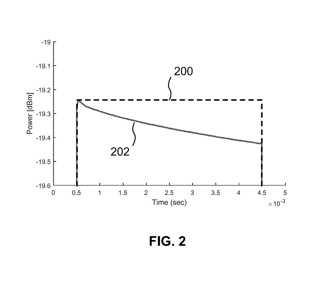
The inability to maintain a flat enough Gain over time for pulses means that corresponding error vector magnitude (EVM) specifications cannot be met as well.
However, by not responding only to self-heating during pulsed operation, such an approach causes too much bias current variation as ambient temperature varies, resulting in poor linearity performance due to under or over-biasing the PA across a full ambient temperature range.

Method used


Image

  • Power amplifier self-heating compensation circuit
  • Power amplifier self-heating compensation circuit
  • Power amplifier self-heating compensation circuit

Examples


example digital

[0065 Sample and Hold Circuit

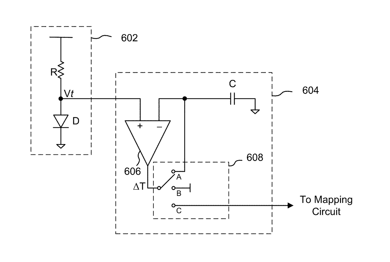
[0066]FIG. 7 is a block diagram of one embodiment of a partially digital S&H circuit 700. The output Vt of one or more temperature sensors 702 is coupled to the input of a counter-DAC-based circuit 704, optionally through an amplifier or buffer 706. More specifically, the temperature sensors 702 are coupled to the plus-input of a summing circuit 708 in this example. The output of the summing circuit 708 is coupled to an optional mapping circuit or may be used directly as a GC signal.

[0067]The output of the summing circuit 708 is also coupled to opposite polarity inputs of two comparators 710a, 710b. The other inputs of the comparators 710a, 710b are coupled to a associated reference voltages +Vref and −Vref. In the illustrated example, a positive reference voltage +Vref (e.g., +0.5LSB) is applied to the negative input of comparator 710a, and a negative reference voltage −Vref (e.g., −0.5LSB) is applied to the positive input of 710b. The outputs of the co...

first embodiment

[0083]FIG. 9 is an indirect temperature measurement gain control signal generation circuit 900. The circuit 900 includes a conventional PA 902 having a Gain control adjustment (e.g., an adjustable bias circuit). Also included is a scaled replica amplifier 904 that, in known fashion, mimics the characteristics and performance behavior of the PA 902, but at a smaller scale (e.g., ⅛ size). The replica amplifier 904 would be fabricated in close proximity to the PA 902 so as to be affected by the self-heating of the PA 902 during pulsed operation. The nominal Gain for the replica amplifier 904 generally would be the same as the nominal Gain for the PA 902 to maximize correlation, but may be set to some other value, such as unity, to simply measurement.

[0084]In the illustrated example, a Reference Signal is applied to the input of the replica amplifier 904 and to a first input of a conventional measurement circuit 906, which may, for example, measure a desired parameter, such as Gain, pow...

second embodiment

[0089]FIG. 10 is an indirect temperature measurement gain control signal generation circuit 1000. In this embodiment, instead of using an AC signal as reference signal as shown in FIG. 9, plus and minus DC voltages (e.g., 0.5V+10 mV=0.51V, and 0.5V−10 mV=0.49V) may be applied to a pair of scaled replica amplifiers 1002a, 1002b located in close proximity to a PA 902. The output of the replica amplifiers 1002a, 1002b may be applied to a first differential amplifier 1004.

[0090]The output of the first differential amplifier 1004 represents the gains of the replica amplifiers 1002a, 1002b, which are assumed to be equal and also equal to the gain of the PA 902. The output signal represents gain because the DC input signals are assumed to be known and accurate. As an example, if +DC=1V+0.1V, and −DC=1V−0.1V, then the difference between the input voltages is equal to (1+0.1)−(1−0.1)=0.2V. If the gain of the replica amplifiers 1002a, 1002b is 10, then the difference of the outputs of the rep...


PUM


Abstract

Temperature compensation circuits and methods for adjusting one or more circuit parameters of a power amplifier (PA) to maintain approximately constant Gain versus time during pulsed operation sufficient to substantially offset self-heating of the PA. Some embodiments compensate for PA Gain “droop” due to self-heating using a Sample and Hold (S&H) circuit. The S&H circuit samples and holds an initial temperature of the PA at commencement of a pulse. Thereafter, the S&H circuit generates a continuous measurement that corresponds to the temperature of the PA during the remainder of the pulse. A Gain Control signal is generated that is a function of the difference between the initial temperature and the operating temperature of the PA as the PA self-heats for the duration of the pulse. The Gain Control signal is applied to one or more adjustable or tunable circuits within a PA to offset the Gain droop of the PA.

Description

CROSS-REFERENCE TO RELATED APPLICATIONS[0001]The present application may be related to U.S. patent application Ser. No. 14 / 272,415, filed May 7, 2014, entitled “Mismatch Detection Using Replica Circuit”, and U.S. patent application Ser. No. 15 / 268,229, filed Sep. 16, 2016, entitled “Cascode Amplifier Bias Circuits”, both of which are assigned to the assignee of the present invention, the entire contents of each of which are incorporated herein by reference.BACKGROUND(1) Technical Field[0002]This invention relates to electronic circuitry, and more particularly to electronic power amplifier circuits.(2) Background[0003]Power amplifiers (PAs) are used in a multitude of electronic systems, particularly radio frequency (RF) systems, such as radios, cellular telephones, WiFi, etc. In a number of radio systems, communication of RF signals is based on time division duplexing (TDD), in which multiple radio transceivers utilize designated time slots within a frequency band to transmit or rece...

Claims


Application Information

Patent Timeline
IPC IPC(8): H03F1/30H03F1/56H03F3/19H03F3/21H03G3/30
CPCH03G3/3042H03F1/30H03F1/56H03F3/19H03F3/21H03G2201/106H03F2200/222H03F2200/318H03F2200/387H03F2200/451H03F1/303H03F1/304H03F3/245H03G3/3036H03F2200/447H03F2200/468
Inventor RANTA, TERO TAPIOBARGROFF, KEITHMURPHY, CHRISTOPHERENGLEKIRK, ROBERT MARK
Owner PSEMI CORP
Why Eureka
Try Eureka