Supercharge Your Innovation With Domain-Expert AI Agents!

Power conversion device, power conversion system, and power conversion method

a technology of power conversion and power conversion method, which is applied in the direction of electric variable regulation, process and machine control, instruments, etc., can solve the problems of high cost and installation space requirements, and achieve the effect of high efficiency

Active Publication Date: 2018-09-04
KYOCERA CORP
View PDF13 Cites 2 Cited by
  • Summary
  • Abstract
  • Description
  • Claims
  • Application Information

AI Technical Summary

Benefits of technology

This approach enables high-efficiency power conversion by utilizing smaller converters in a coordinated manner, reducing the overall capacity and cost requirements while ensuring maximum output and input capabilities, thereby optimizing energy distribution and storage.

Problems solved by technology

However, some power conversion devices such as a hybrid type power conversion device include a plurality of converters, and higher efficiency is required in terms of cost and installation space.

Method used


Image

  • Power conversion device, power conversion system, and power conversion method
  • Power conversion device, power conversion system, and power conversion method
  • Power conversion device, power conversion system, and power conversion method

Examples


first embodiment

[0034][First Embodiment]

(1) Entire Configuration of Power Conversion System

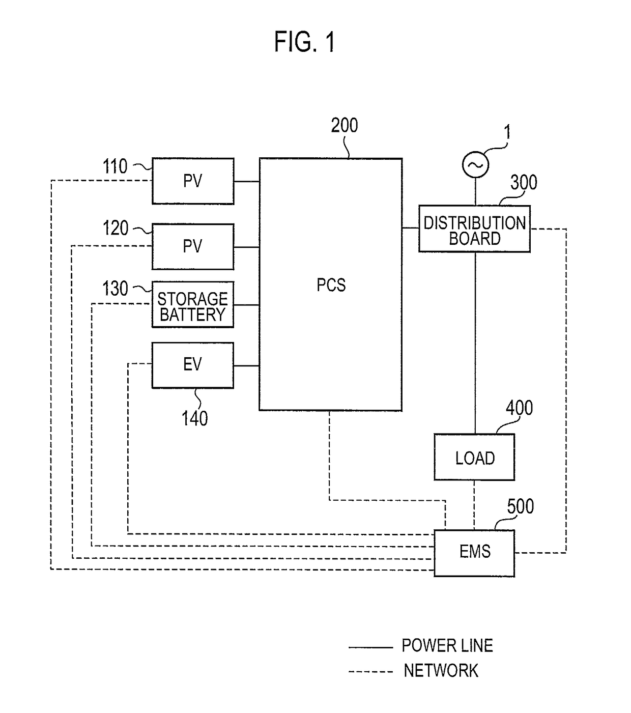
[0035]FIG. 1 is a diagram showing the entire configuration of a power conversion system according to a first embodiment. In the following figure, a power line is shown by a solid line, and a signal line is shown by a broken line. The signal line may not just be wired but wireless.

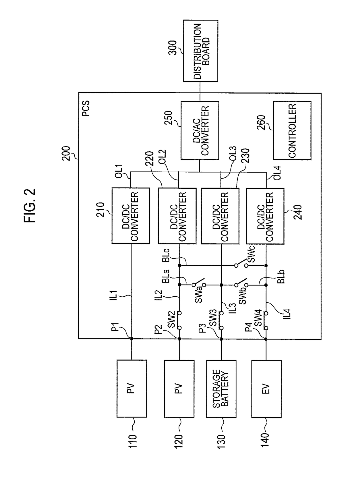
[0036]As shown in FIG. 1, the power conversion system according to the first embodiment is provided with photovoltaic cells (PVs) 110 and 120, a storage battery 130, an electric vehicle (EV) 140, a power conditioner (PCS) 200, a distribution board 300, a load 400, and EMS 500, at the consumer's facility who receives supply of AC power from a grid 1.

[0037]Each of the PVs 110 and 120 is an example of a distributed power source, and is a solar light power generation device (PhotoVoltaic device) which generates power by receiving solar light. The PVs 110 and 120 output DC power generated thereby to the PCS 200. Each of the PVs 110 and 12...

second embodiment

[0095][Second Embodiment]

[0096]A power conversion system according to a second embodiment of the present invention will be described, below. FIG. 6 is a block diagram of EMS 500 according to the second embodiment of the present invention. Mainly, differences from the first embodiment are mainly described, below.

[0097]As shown in FIG. 6, the EMS 500 has an indoor communication unit 510, an outdoor communication unit 520, a controller 530, and a storage unit 540.

[0098]The indoor communication unit 510 transmits and receives various types of signals to and from a device that is compatible with near field communication such as WiFi and connected to the indoor communication unit 510 through a signal line. For example, the indoor communication unit 510 receives information on a device type, power consumption, and the like of the load 400.

[0099]In the second embodiment, the indoor communication unit 510 receives various types of information on the PVs 110 and 120, the storage battery 130, ...


PUM


Abstract

A PCS (200) converts the output power from a plurality of distributed power supplies or the supply power to the distributed power supplies. The PCS (200) is provided with a plurality of converters for converting said output power or said supply power. In a first state, the converters convert the respective outputs of the distributed power supplies. In a second state, the converters perform a conversion on the output or input of at least one distributed power supply by using multiple converters.

Description

TECHNICAL FIELD[0001]The present invention relates to a power conversion device that converts output of a distributed power source, a power conversion system, and a power conversion method.BACKGROUND ART[0002]In recent years, a distributed power source has been introduced among consumer's facilities of grid power. Examples of distributed power sources include a photovoltaic cell, a fuel cell, or a storage battery. Output power from these distributed power sources are DC / AC converted by a power conversion device to be supplied to a load. The power conversion device includes a DC / DC converter that boosts a voltage of DC power output by the distributed power source and a DC / AC converter that converts the DC power of which the voltage is boosted into AC power.[0003]Further, a hybrid type power conversion device compatible with a plurality of distributed power sources is known. The hybrid type power conversion device includes a DC / DC converter specified by each distributed power source a...

Claims


Application Information

Patent Timeline
Patent Type & Authority Patents(United States)
IPC IPC(8): H02J3/38H02M3/155B60L11/18H02M7/44H02M7/48H02M3/04H02J7/00H02M1/00H02J7/35
CPCH02J3/383H02J7/007H02M3/04H02M3/155H02M7/44H02M7/48B60L11/1812Y04S10/126B60L2210/10B60L2230/22H02J7/35H02M2001/007Y02E10/563Y02E60/721Y02T10/7005Y02T10/7094Y02T10/7216Y02T10/92Y02T90/12Y02T90/127Y02T90/14B60L53/22B60L53/51H02J2310/48H02J2300/24H02J3/381Y02E10/56Y02T10/7072Y02T10/72Y02T10/70H02M1/007Y02E60/00
Inventor TAKENAKA, TETSUYA
Owner KYOCERA CORP
Features
  • R&D
  • Intellectual Property
  • Life Sciences
  • Materials
  • Tech Scout
  • Unparalleled Data Quality
  • Higher Quality Content
  • 60% Fewer Hallucinations
Learn More