
Near-infrared cut filter

a filter and near-infrared technology, applied in the field of near-infrared filter, can solve the problems of insufficient performance of near-infrared shielding light and wavelength band (630 nm to 700 nm) required for imaging a dark part more brightly, and achieve excellent near-infrared shielding properties, the effect of reducing size and thickness

Active Publication Date: 2018-09-25
ASAHI GLASS CO LTD
View PDF28 Cites 9 Cited by
  • Summary
  • Abstract
  • Description
  • Claims
  • Application Information

AI Technical Summary

Benefits of technology

The solution provides excellent near-infrared shielding with high visible light transmission, enabling size and thickness reduction of imaging devices while maintaining high heat resistance and manufacturing flexibility, effectively addressing the limitations of existing filters.

Problems solved by technology

However, in addition to being expensive, a glass filter of light-absorbing type may not sufficiently exhibit a function based on components of the glass when being made thin, and there has been a problem that it cannot sufficiently respond to requirements of size reduction and thickness reduction of an imaging device of late years.
However, in these conventional optical filters for imaging devices, performance for shielding light of wavelengths in the near-infrared region and a transmitting property of wavelength band (630 nm to 700 nm) required for imaging a dark part more brightly are insufficient.
Moreover, since there is also a constraint on layer formation such that the function of the solid-state image sensing device should not be hindered, currently an optical filter having a sufficient near-infrared cut filter function has not been obtained.
The dye described in Patent Reference 2, although having high transmittance of 630 nm to 700 nm as compared to conventional near-infrared absorbing dye, this transmittance is not sufficiently high, and solubility to the resin is also low.
Thus, there has been a problem that the near-infrared absorbing layer cannot be made sufficiently thin.

Method used


Image

  • Near-infrared cut filter
  • Near-infrared cut filter
  • Near-infrared cut filter

Examples


example 1 to example 75

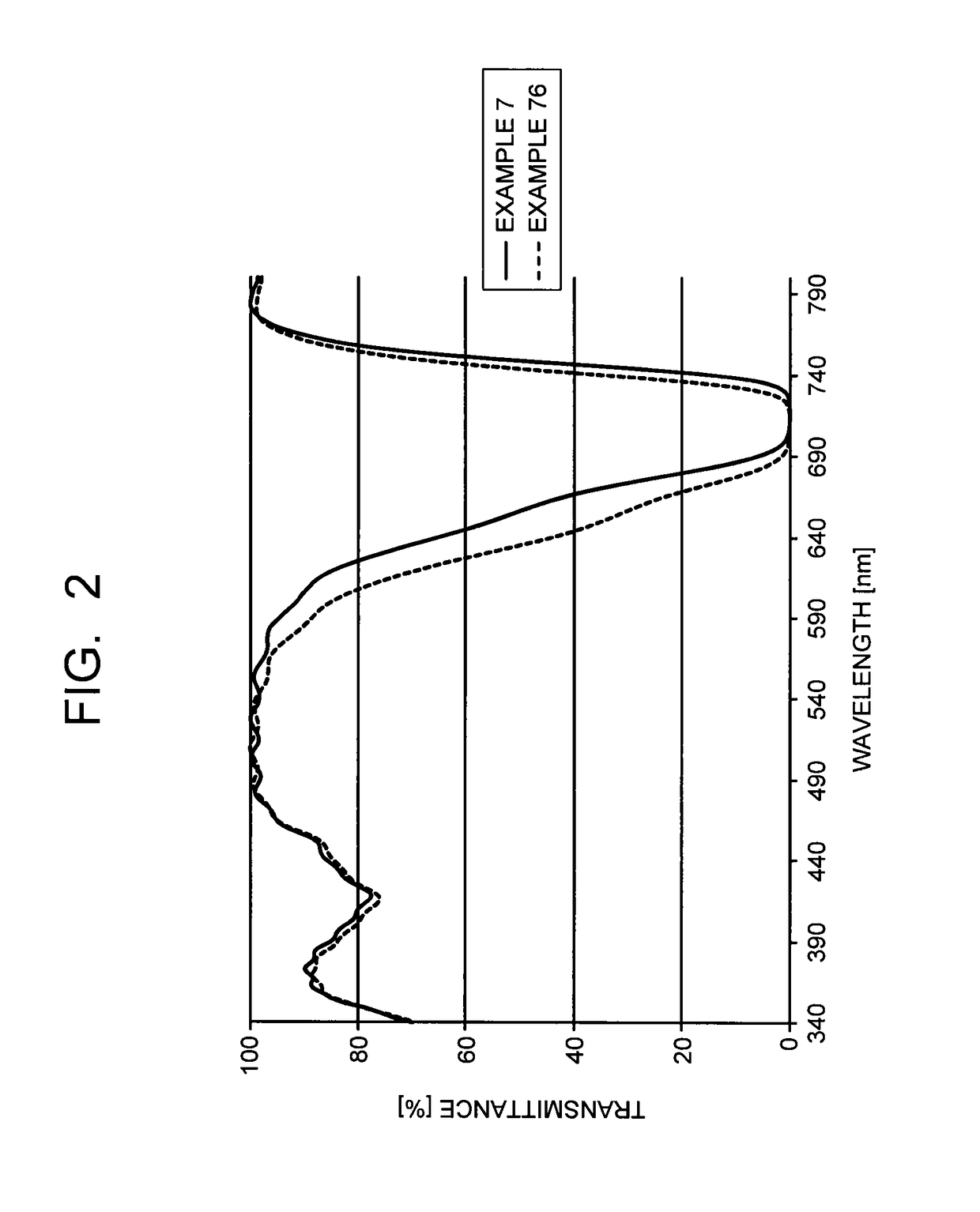
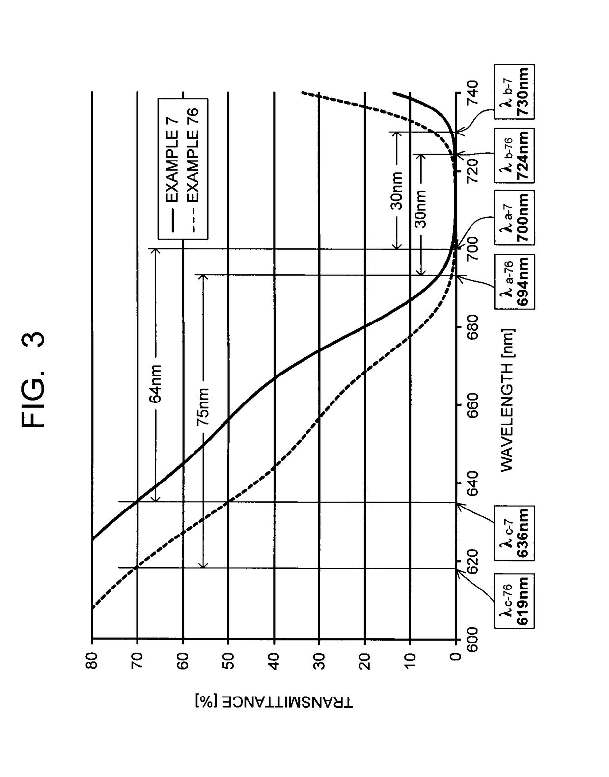
[0266]As described in Table 4, one of the dyes (A11-1) to (A11-19) and a 15 mass % cyclohexanone solution of the polyester resin were mixed, and stirred and solved at room temperature to obtain a coating liquid. In any case, the dyes (A11-1) to (A11-19) were mixed by a content which causes (λb−λa) (absorption width when the transmittance is 1% or less) defined in the above condition (ii-2) to be 30 nm with a film thickness of 3 μm or less to 100 parts by mass of the polyester resin. As the polyester resin, B-OKP2 (product name, made by Osaka Gas Chemicals Co., Ltd., refractive index 1.64) was used.

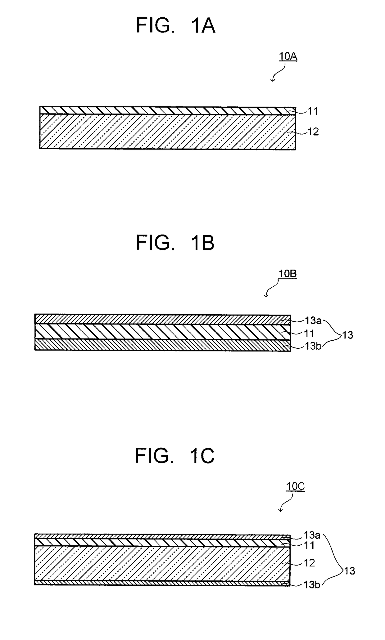
[0267]The coating liquid obtained above was applied on a glass plate by a spin coat method and dried at 90° C. for five minutes, and thereafter an obtained sample was further dried at 150° C. for 60 minutes, thereby obtaining NIR filters of Example 1 to Example 17. The film thicknesses of the near-infrared absorbing layers of the obtained NIR filters 1 to 17 were all 2.7 μm.

[0268]NIR filte...

example 76 to example 109

[0277]As described in Table 7 and Table 8, one of the dyes (A11-20) to (A11-27) and the transparent resin (B) were used to obtain NIR filters 76 to 109 of Example 76 to Example 109. The film thicknesses of the near-infrared absorbing layers of the respective NIR filters are the same film thicknesses as those of respective examples of the examples that use the same transparent resin (B).

[0278]

(1) Absorption Characteristics

[0279]Regarding transmittance (% / nm) of the NIR filters 1 to 109 obtained above, transmission spectra were measured and calculated by using an ultraviolet visible light spectrophotometer (U-4100 type spectrophotometer made by Hitachi High-Technologies Corporation). Analysis results of transmission spectra of the near-infrared absorbing layers which the NIR filters have are presented in Table 4, Table 5 and Table 6 for the NIR filters 1 to 25, 26 to 51, 52 to 75, respectively, and are presented in Table 7 and Table 8 for the NIR filters 76 to 94, 95 to 109, respectiv...

example 110

[0301]The near-infrared absorbing layer was formed on a glass plate similarly to Example 7 except that a glass plate on which the selected wavelength shielding layer is formed was used on a face opposite to an application face of the coating liquid for forming the near-infrared absorbing layer. Moreover, the antireflection layer was formed on the near-infrared absorbing layer, so as to obtain the NIR filter 110. The film thickness in the selected wavelength shielding layer in its entirety was approximately 8.9 μm, and the film thickness in the antireflection layer in its entirety was approximately 0.34 μm. The transmittance of the obtained NIR filter 110 was measured, and 20% shifts (30 degrees) and (40 degrees) were obtained. Results thereof are presented in Table 9 together with structures of the near-infrared absorbing layer. FIG. 6 illustrates transmission spectra of light with incident angles of 0 degree, 30 degrees and 40 degrees of the wavelength region of 660 nm to 690 nm in...


PUM

PropertyMeasurementUnit
refractive indexaaaaaaaaaa
wavelengthaaaaaaaaaa

Abstract

There is provided a near-infrared cut filter which has a visible light transmitting property and a near-infrared shielding property both at high levels by that its transmission spectrum has a steep inclination in the vicinity of the boundary between the visible light and the near-infrared, and which can also be sufficiently reduced in size and thickness. The near-infrared cut filter has a near-infrared absorbing layer which contains a near-infrared absorbing dye containing at least one dye in which a condensed ring structure containing at least a benzene ring and a ring having nitrogen atom is bonded to both sides of a squarylium skeleton and which have a carboxylic acid amide structure at a second position of the benzene ring (where the carboxylic acid has a substituent having 5 to 25 having one or more branches), and a transparent resin with a refractive index of 1.45 or more.

Description

CROSS-REFERENCE TO RELATED APPLICATIONS[0001]This application is a continuation of prior International Application No. PCT / JP2013 / 082683 filed on Dec. 5, 2013, which is based upon and claims the benefit of priority from Japanese Patent Applications No. 2012-267054 filed on Dec. 6, 2012, and No. 2013-120894 filed on Jun. 7, 2013; the entire contents of all of which are incorporated herein by reference.TECHNICAL FIELD[0002]The present invention relates to a near-infrared cut filter having a near-infrared shielding effect.BACKGROUND ART[0003]In recent years, optical filters which sufficiently transmit light in a visible wavelength region but shield light in a near-infrared wavelength region have been used for various applications.[0004]For example, a solid-state image sensing device (such as CCD or CMOS) is used in an imaging device such as a digital still camera and a digital video camera. In order to make sensitivity of the solid-state image sensing device close to visibility of a hu...

Claims


Application Information

Patent Timeline
Patent Type & Authority Patents(United States)
IPC IPC(8): F21V9/04G02B1/04G02B5/28G02B5/20G02B5/22C08K5/3417C09B57/00C09B67/22
CPCG02B5/282C08K5/3417C09B57/007C09B67/0034G02B1/04G02B5/223G02B5/208C08L2666/70C09K3/00
Inventor SHIONO, KAZUHIKOARISHIMA, HIROYUKIKONISHI, TEPPEIHOTAKA, HIROKI
Owner ASAHI GLASS CO LTD
Learn More