
Method for operating an electric machine

a technology of electric machines and electric drives, applied in the direction of electric generator control, instruments, testing circuits, etc., can solve the problems of overvoltage, damage to electric drives, relative ground potential can rise or fall in an uncontrolled manner, etc., to achieve effective and reliable, safeguard the effect of conventional overvoltage protection functions and improve the effect of reliability

Active Publication Date: 2018-10-16
ROBERT BOSCH GMBH +1
View PDF15 Cites 1 Cited by
  • Summary
  • Abstract
  • Description
  • Claims
  • Application Information

AI Technical Summary

Benefits of technology

The patent is about a method that ensures the electric drive is safe in case of a ground strape break. This method is cost-effective and can be implemented using software. It uses a special emergency operation to stabilize the ground potential, preventing any uncontrolled rise or drop in voltage. This method can be executed using various computer programs and can be downloaded through computer networks. Overall, the technology provides a safer and reliable solution for driving electric vehicles.

Problems solved by technology

The relative ground potential can therefore rise or drop in an uncontrolled manner.
A ground strap break may result in damage to the electric drive.
An overvoltage may occur if a ground strap break occurs in a regenerative operation of the electric drive.
A ground strap break during an operation of the electric drive as motor may lead to a critical voltage of the logic circuit, which could lead to a reset and loss of control over the electric drive.
The logic circuit must have a voltage supply at all times. If the logic circuit loses its energy supply, a faulty or even destructive functionality of the logic circuit may be the result.
In the special case of a ground strap break, the logic circuit is unable to achieve its functionality.
As a result, no current can flow out of the electric machine, i.e., no current can “leave” the electric machine.
These currents thus result in a change in the relative ground potential.
Changes to the existing structural elements or additional structural elements may possibly be necessary only for sensing the ground strap break, but not for stabilizing the relative ground potential as such.
However, before the ground differential voltage becomes too low and an excessively high, critical voltage is present at the logic circuit, the electric drive switches into the noncurrent-delivering operating state.
In the non-current-delivering operating state, no electrical energy is generated, however.
If a ground strap break occurs when the electric machine happens to be operated as a generator in the regular operating mode, the relative ground potential becomes more negative and a generator voltage rises as a result.
This usually leads to the triggering of conventional overvoltage protection functions.
This may lead to a critical voltage of the logic circuit, which could result in a reset and in a loss of all control over the electric drive.

Method used


Image

  • Method for operating an electric machine
  • Method for operating an electric machine
  • Method for operating an electric machine

Examples


Embodiment Construction

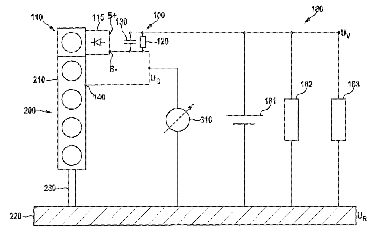
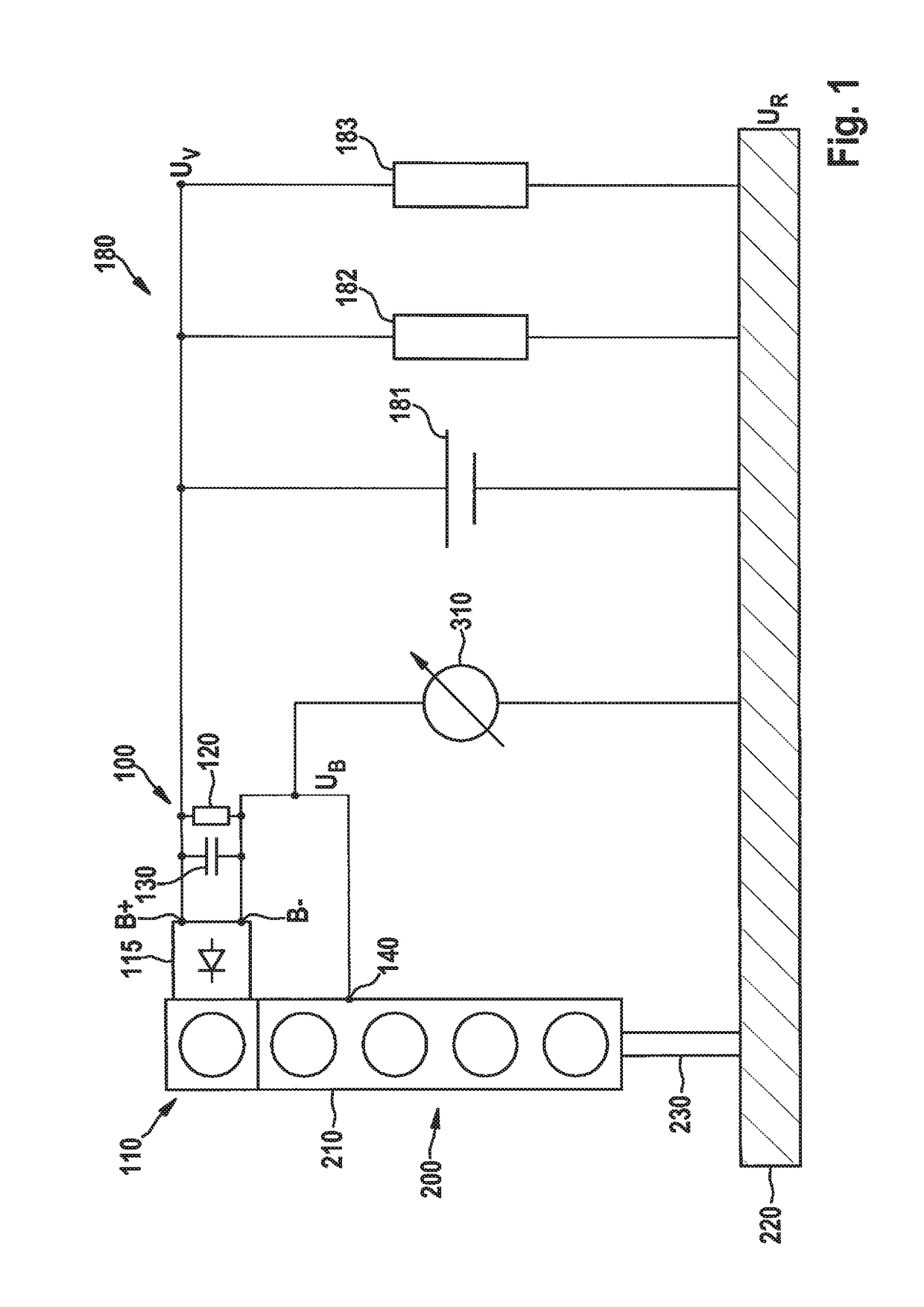
[0048]FIG. 1 schematically illustrates an electric drive, which i denoted by 100. Electric drive 100 is linked to an internal combustion engine 200 of a motor vehicle. Electric drive 100 is equipped with an electric machine 110, which can be operated both as a generator and a motor. For this purpose, the electric machine has, inter alia, a power inverter 115 including electrical switches, especially semiconductor switches. Power inverter 115 of electric machine 110 has DC voltage terminals 33+, B− for a vehicle electrical system 180 on the one side, and AC voltage terminals for the electrical phases of the electric machine on the other side.

[0049]To actuate electric machine 110, in particular power inverter 115, the electric machine has a logic circuit 120. An intermediate circuit capacitor 130 is connected in parallel to logic circuit 120.

[0050]For example, vehicle electrical system 180 may include an energy store 181 and electrical consumers 181, 182. A positive potential of vehic...


PUM


Abstract

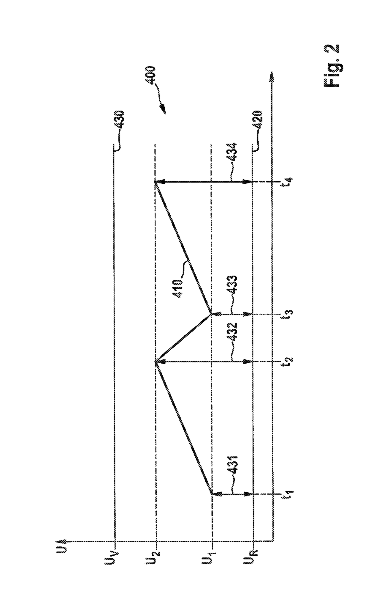
A method for operating an electric machine having a power inverter, which is electrically connected to a relative ground potential, and a ground differential voltage between the relative ground potential and a reference ground potential is monitored, and if the ground differential voltage reaches an upper limit value, the electric machine is operated in a current-delivering operating state, and if the ground differential voltage reaches a lower limit value, the electric machine is operated in a non-current-delivering operating state.

Description

FIELD[0001]The present invention relates to a method for operating an electric machine.BACKGROUND INFORMATION[0002]Electric drives generally have two components. On the one hand, the electric drive has an electric machine which converts mechanical energy into electrical energy or vice versa (electromechanical transformer). The electric machine may be operated both in generator mode as a generator and in motor mode as an (electric) motor. On the other hand, the electric drive has a power inverter or an inverter / rectifier circuit. The power inverter converts an electrical AC voltage into an electric DC voltage or vice versa (electric transformer). In most cases such an inverter has electric switches, often power semiconductors such as MOSFETs, and is actuated by a logic circuit. The power inverter and logic circuit are jointly also referred to as inverter.[0003]For construction-related reasons, electric machines are usually connected via their housing to the engine block of the intern...

Claims


Application Information

Patent Timeline
Patent Type & Authority Patents(United States)
IPC IPC(8): G01R31/14B60L15/20B60L7/14B60L3/04H02H5/10B60L3/00H02P9/00G01R31/25H02P6/12H02P29/024B60L11/14G01R27/08B60L50/16
CPCH02P9/006B60L3/04B60L7/14B60L11/14B60L15/20H02H5/105H02P6/12H02P29/0241B60L3/0061Y02T10/7275B60L2210/40B60L2240/427B60L2240/429Y02T10/645Y02T10/70Y02T10/7077Y02T10/7241B60L50/16Y02T10/64Y02T10/7072Y02T10/72
Inventor ESCHENHAGEN, MARC
Owner ROBERT BOSCH GMBH
Learn More