Multilayer ceramic capacitor, mounting structure of multilayer ceramic capacitor, and taped electronic component array
a multi-layer ceramic and capacitor technology, applied in the direction of printed circuit non-printed electric components association, sustainable manufacturing/processing, final product manufacturing, etc., can solve the problems of difficult to ensure moisture resistance, peeling may occur in the interface between the internal electrode and the dielectric ceramic layer, etc., to achieve the effect of reducing the connection resistance between the external electrode and the internal electrode, improving the connection efficiency and improving the high frequency region
- Summary
- Abstract
- Description
- Claims
- Application Information
AI Technical Summary
Benefits of technology
Problems solved by technology
Method used
Image
Examples
first preferred embodiment
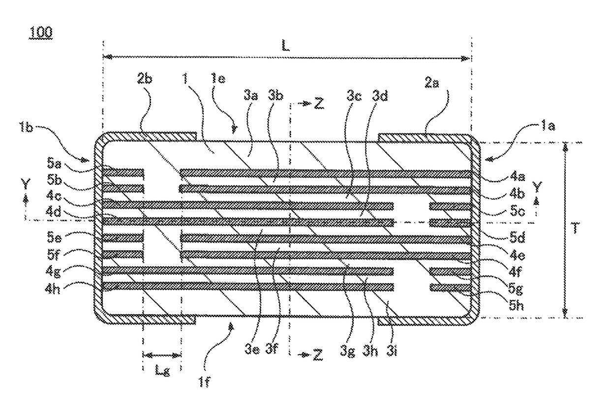
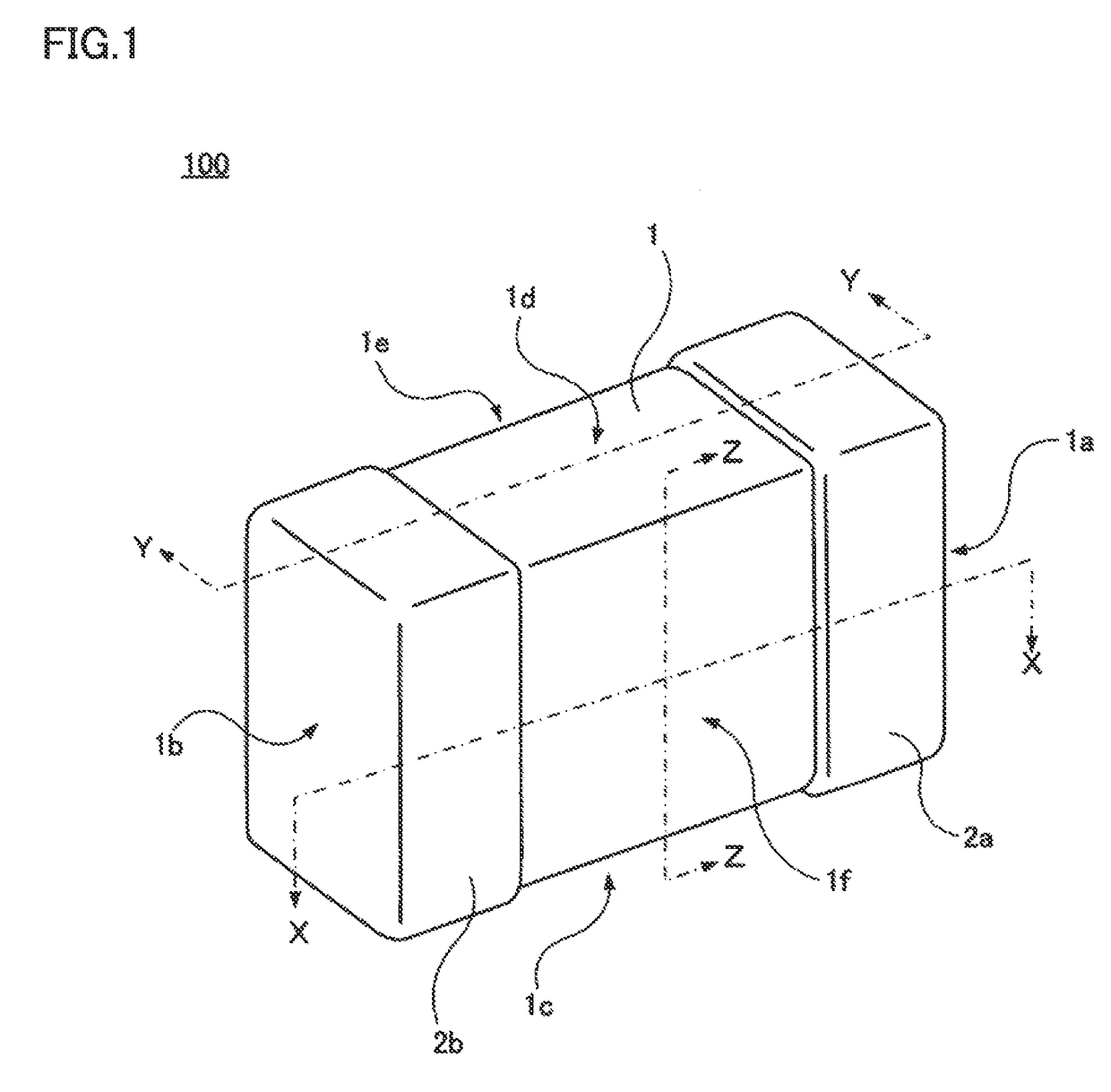
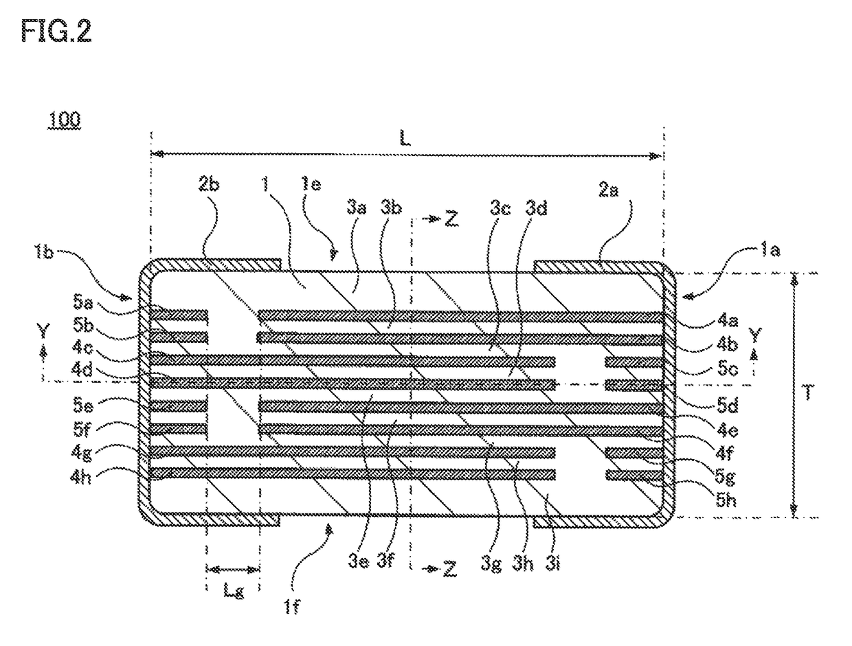
[0036]FIG. 1 is a perspective view showing a multilayer ceramic capacitor according to the first preferred embodiment of the present invention. FIG. 2 is a cross-sectional view of the multilayer ceramic capacitor according to the first preferred embodiment of the present invention, as seen in the direction indicated by line arrows X-X in FIG. 1. FIG. 3 is a cross-sectional view of the multilayer ceramic capacitor according to the first preferred embodiment of the present invention, as seen in the direction indicated by line arrows Y-Y in each of FIGS. 1 and 2. FIG. 4 is a cross-sectional view of the multilayer ceramic capacitor according to the first preferred embodiment of the present invention, as seen in the direction indicated by line arrows Z-Z in each of FIGS. 1 to 3.
[0037]As shown in FIGS. 1 to 4, a multilayer ceramic capacitor 100 includes a stacked body 1. The stacked body 1 preferably has a rectangular or substantially rectangular parallelepiped shape including a first end...
second preferred embodiment
[0098]A multilayer ceramic capacitor 200 according to the second preferred embodiment of the present invention will be hereinafter described. FIG. 10 is a cross-sectional view showing the configuration of a multilayer ceramic capacitor according to the second preferred embodiment of the present invention.
[0099]In the multilayer ceramic capacitor 100 according to the first preferred embodiment shown in each of FIGS. 1 to 4, two adjacent internal electrodes 4a and 4b are connected to one external electrode 2a, two adjacent internal electrodes 4c and 4d are connected to the other external electrode 2b, two adjacent internal electrodes 4e and 4f are connected to one external electrode 2a, and two adjacent internal electrodes 4g and 4h are connected to the other external electrode 2b. In this way, every two internal electrodes selected from internal electrodes 4a to 4h are defined as one set and connected to external electrode 2a or external electrode 2b. On the other hand, in multilayer...
experimental examples
[0107]The following experimental simulations were performed in order to confirm the effectiveness of the various preferred embodiments of the present invention.
[0108]First, as an Example, five types of multilayer ceramic capacitors each having the structure of the multilayer ceramic capacitor 100 according to the first preferred embodiment described above were formed. These five types of multilayer ceramic capacitors each had an electrostatic capacitance of about 0.7 pF, about 1.0 pF, about 1.5 pF, about 2.0 pF, and about 3.0 pF, respectively, for example.
[0109]In the Example, the stacked body 1 was configured to have a length dimension L of about 0.4 mm, a width dimension W of about 0.3 mm, and a thickness dimension T of about 0.2 mm.
[0110]Also, in the Example, the internal electrodes 14a to 14h each were configured to have a width dimension WE of about 0.2 mm that was about 68% of the width dimension W of stacked body 1. The thickness dimension TE of each of the internal electrode...
PUM
| Property | Measurement | Unit |
|---|---|---|
| thickness | aaaaa | aaaaa |
| thickness | aaaaa | aaaaa |
| thickness | aaaaa | aaaaa |
Abstract
Description
Claims
Application Information
 - R&D
- Intellectual Property
- Life Sciences
- Materials
- Tech Scout
- Unparalleled Data Quality
- Higher Quality Content
- 60% Fewer Hallucinations
Browse by: Latest US Patents, China's latest patents, Technical Efficacy Thesaurus, Application Domain, Technology Topic, Popular Technical Reports.
© 2025 PatSnap. All rights reserved.Legal|Privacy policy|Modern Slavery Act Transparency Statement|Sitemap|About US| Contact US: help@patsnap.com


