Methods and systems of treating a particle beam and performing mass spectroscopy

a particle beam and mass spectroscopy technology, applied in the direction of electrical equipment, charge exchange devices, electric discharge tubes, etc., can solve the problems of sample ionisation efficiency, low, and most sample measurement cost, and achieve the effect of maximizing both molecule suppression and charge exchange and facilitating the subsequent utilisation of remaining species

Active Publication Date: 2018-11-13
THE UNIV COURT OF THE UNIV OF GLASGOW
View PDF13 Cites 1 Cited by
  • Summary
  • Abstract
  • Description
  • Claims
  • Application Information

AI Technical Summary

Benefits of technology

[0016]The present inventors have realised that thick-stripper physics also produces a useful amount of negative ions so that known metal vapour charge exchange cells can be improved upon whilst addressing several practical disadvantages of known metal vapour charge exchange cells, identified by the inventors. It has surprisingly been found that the adoption of thick-stripper physics and benign gases makes charge exchange cells additionally effective molecule suppressors without compromising negative ionisation efficiency at the level of suppression achieved. Furthermore, the creation, containment and metering of metal vapours is cumbersome, imprecise and difficult, typically requiring specialist equipment. Still further, metal vapours are electrically conducting if condensed and so pose a challenge when used in systems involving high electric fields such as mass spectrometers.
[0045]The particle beam is then passed through a charge exchange cell. The charge exchange cell preferably contains sufficiently thick isobutane or similarly effective other gas to both convert positive incident 14C ions to negative ions and to suppress 13CH and 12CH2 interferences, thereby providing the treated particle beam.

Problems solved by technology

Typically, most of a sample measurement cost is in making the material to be analysed compatible with the ion source technology.
Such negative ion sources typically operate on difficult-to-control Cs metallic vapour in order to achieve their best, but still low, sample ionisation efficiency.

Method used


Image

  • Methods and systems of treating a particle beam and performing mass spectroscopy
  • Methods and systems of treating a particle beam and performing mass spectroscopy
  • Methods and systems of treating a particle beam and performing mass spectroscopy

Examples


Embodiment Construction

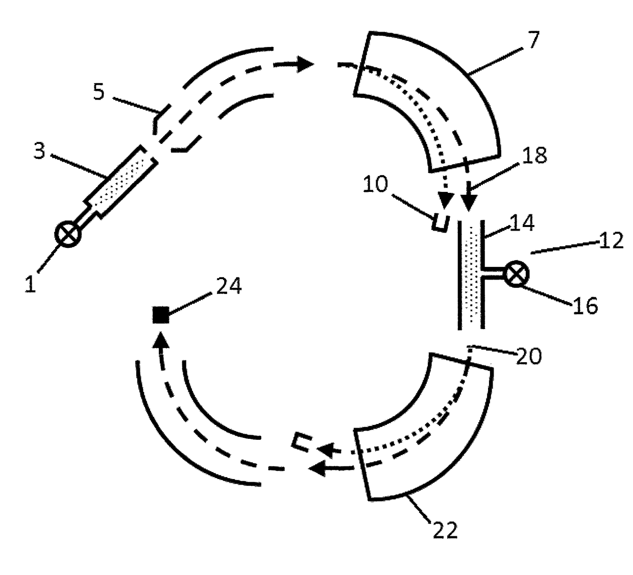
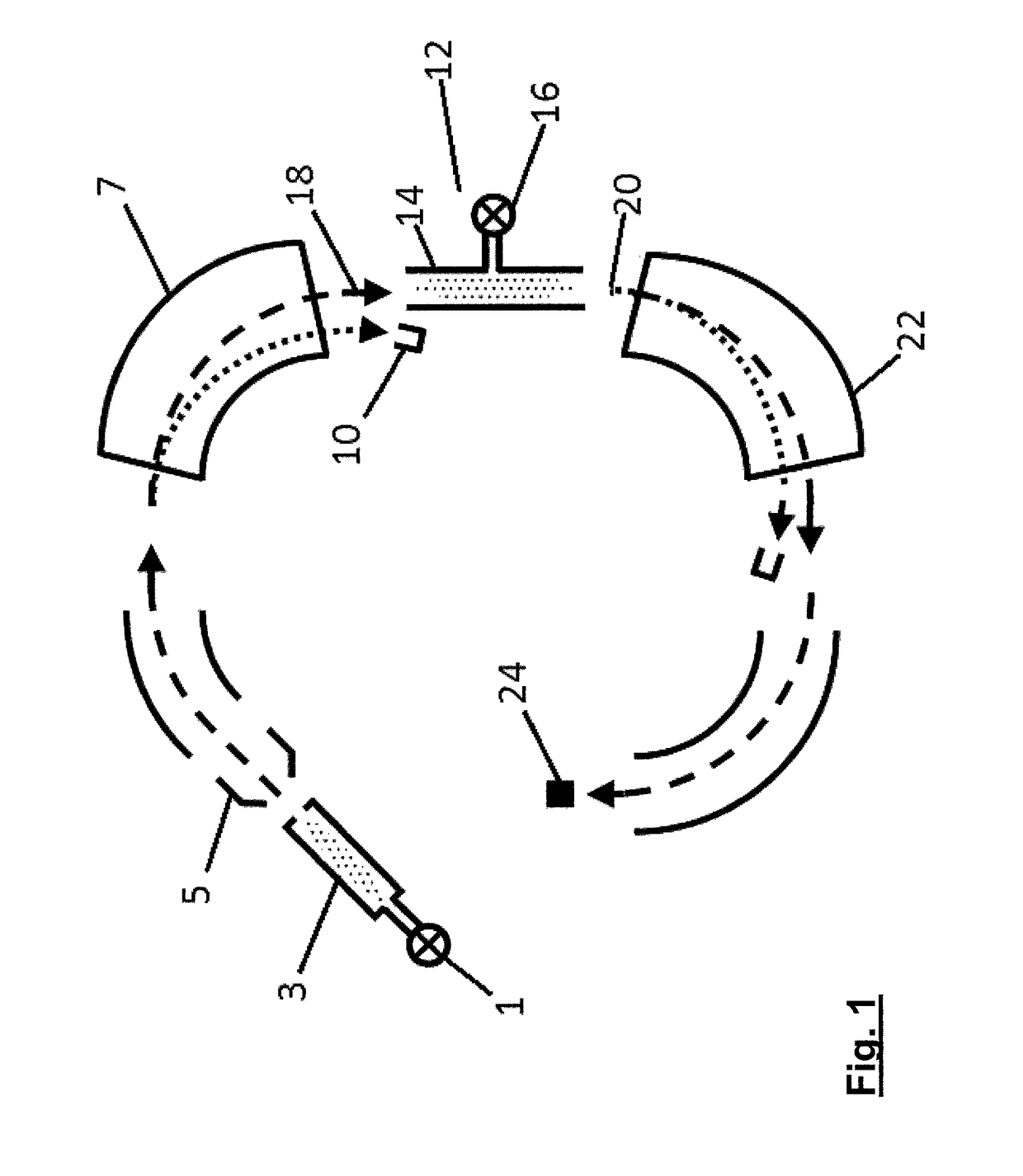
[0053]FIG. 1 shows a schematic of radiocarbon measurement according to an embodiment of the invention. Beginning in the electron cyclotron resonance (ECR) ion source, interferences to 14C detection are increasingly suppressed until reliable radiocarbon detection is possible. In FIG. 1, the two mass spectrometers each comprise an electrostatic spherical analyser (ESA) and dipole magnet. Component electrical-biasing is not shown but by manipulating the beam energy the carbon stable isotopes can be quantified with Faraday cup detectors.

[0054]The mass spectrometer components shown in FIG. 1 are given by way of example only. They may be differently ordered, added to or subtracted from, and other components such as ion velocity Wien-filters may be substituted.

[0055]As is the case of conventional AMS, the 14C is measured in ratio to stable 12C and / or 13C in the common beam from the ion source. The first spectrometer separates the radiocarbon from stable carbon ions which can then be measur...


PUM


Abstract

A method of treating a particle beam is disclosed, of interest in particular for mass spectrometry for 14C. A particle beam including positive ions is passed through a charge exchange cell containing a target gas. The target gas is electrically insulating at room temperature and pressure. At least some of the positive ions of the particle beam are converted to negative ions by interaction with the target gas. The particle beam incident at the charge exchange cell includes molecules and / or molecular ions which interact with the target gas to reduce the concentration of molecules as a result of repeated collisions with particles of the target gas. A corresponding mass spectrometry system is also disclosed.

Description

RELATED APPLICATIONS[0001]This application is a 35 U.S.C. § 371 national phase application of PCT / GB2015 / 051872 (WO 2015 / 198069), filed on Jun. 26, 2015, entitled “Particle Beam Treatment” which application claims priority to United Kingdom Application No. 1411407.8, filed Jun. 26, 2014, which is incorporated herein by reference in its entirety.BACKGROUND TO THE INVENTION[0002]Field of the Invention[0003]The present invention relates to a method of treating a particle beam and to an apparatus for treating a particle beam. The invention has particular applicability for changing the charge state of particles in the particle beam. The invention has applications in various fields such as in accelerator mass spectrometry (AMS). The present invention also relates to a method of performing mass spectrometry and to a system for performing mass spectrometry.Related Art[0004]Ultrasensitive mass spectrometry (analysis techniques for determining sample constituents) can require the suppression ...

Claims


Application Information

Patent Timeline
Patent Type & Authority Patents(United States)
IPC IPC(8): H01J49/00G21K1/14
CPCG21K1/14H01J49/0086
Inventor FREEMAN, STEWARTSHANKS, RICHARD
Owner THE UNIV COURT OF THE UNIV OF GLASGOW
Why Eureka
Try Eureka