Method for depositing a target material onto a organic electrically functional material

a technology of electrically functional materials and target materials, which is applied in the direction of vacuum evaporation coating, organic semiconductor devices, coatings, etc., can solve the problems of reduced light produced when powered, material functionality loss or significant reduction, and even complete failure, so as to achieve the effect of lowering the pressure regim

Active Publication Date: 2018-11-13
LAM RES CORP
View PDF7 Cites 0 Cited by
  • Summary
  • Abstract
  • Description
  • Claims
  • Application Information

AI Technical Summary

Benefits of technology

[0030]With a physical depositing method a near vacuum environment is created in which the depositing is performed. By controlling the vacuum or the pressure in this environment, the impact velocity of the particles can be controlled. When a higher pressure regime is used, the particles of the target material in the vapor plume are slowed down more, such that the impact on the substrate is less violent and the sensit...

Problems solved by technology

Such organic electrically functional materials are typically damaged by known physical vapor deposition methods to such an extent, that the functionality of the mate...

Method used


Image

  • Method for depositing a target material onto a organic electrically functional material
  • Method for depositing a target material onto a organic electrically functional material
  • Method for depositing a target material onto a organic electrically functional material

Examples


first embodiment

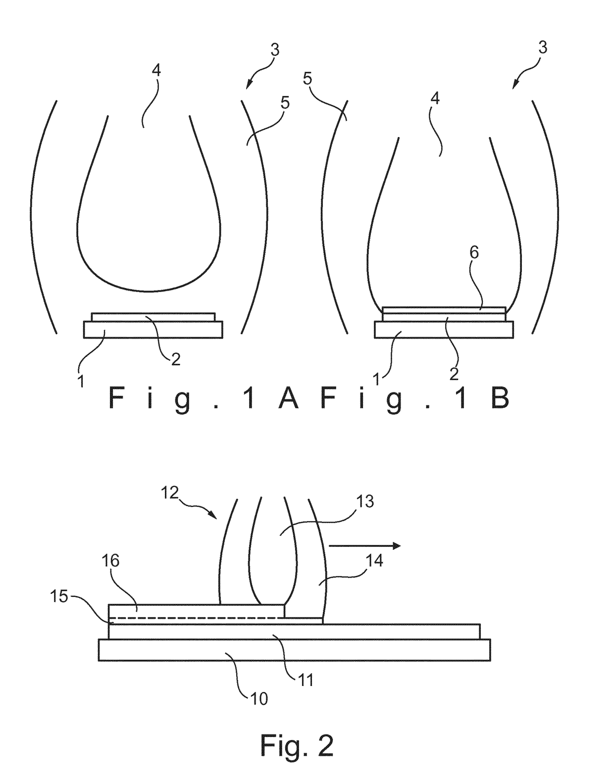
[0054]FIG. 1A shows a first step of the method according to the invention. A substrate 1 is provided with a layer of organic electrically functional material 2. A vapor plume 3 with particles of a target material is generated with a pulsed laser deposition method. This vapor plume 3 has a core 4 and an envelope 5.

[0055]By controlling the pressure regime in which the vapor plume 3 is generated, the reach of the plume 3 and the impact of the particles within the plume 3 can be controlled. In the step shown in FIG. 1A, the pressure is relative high, such that the kinetic energy of the particles within the plume 3 is reduced and the particles have a ‘soft landing’ on the surface of the organic electrically functional material and form a first layer of target material 6.

[0056]In the step shown in FIG. 1B, the pressure is reduced, such that the particles within the plume 3 keep their kinetic energy and are deposited on top of the first layer of target material 6 in the conventional way to...

second embodiment

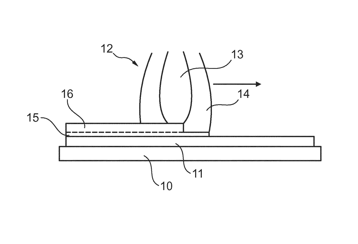
[0057]FIG. 2 shows the method according to the invention. A substrate 10 is provided with a layer 11 of a organic electrically functional material. Furthermore, a vapor plume 12 is generated. This vapor plume 12 has a core 13 with particles having a relatively high velocity, and an envelope 14 around the core 13 with particles with a relatively low velocity.

[0058]The plume 12 is moved over the surface of the organic electrically functional material 11. The envelope 14 deposits first a first layer 15 of target material of the organic material 11. The trailing core 13 then deposits a second layer 16 on the already deposited first layer 15. As the first layer 15 and second layer 16 are deposited with the same target material particles, a virtually homogeneous layer of target material on top of the organic material 11 is created.

embodiment 20

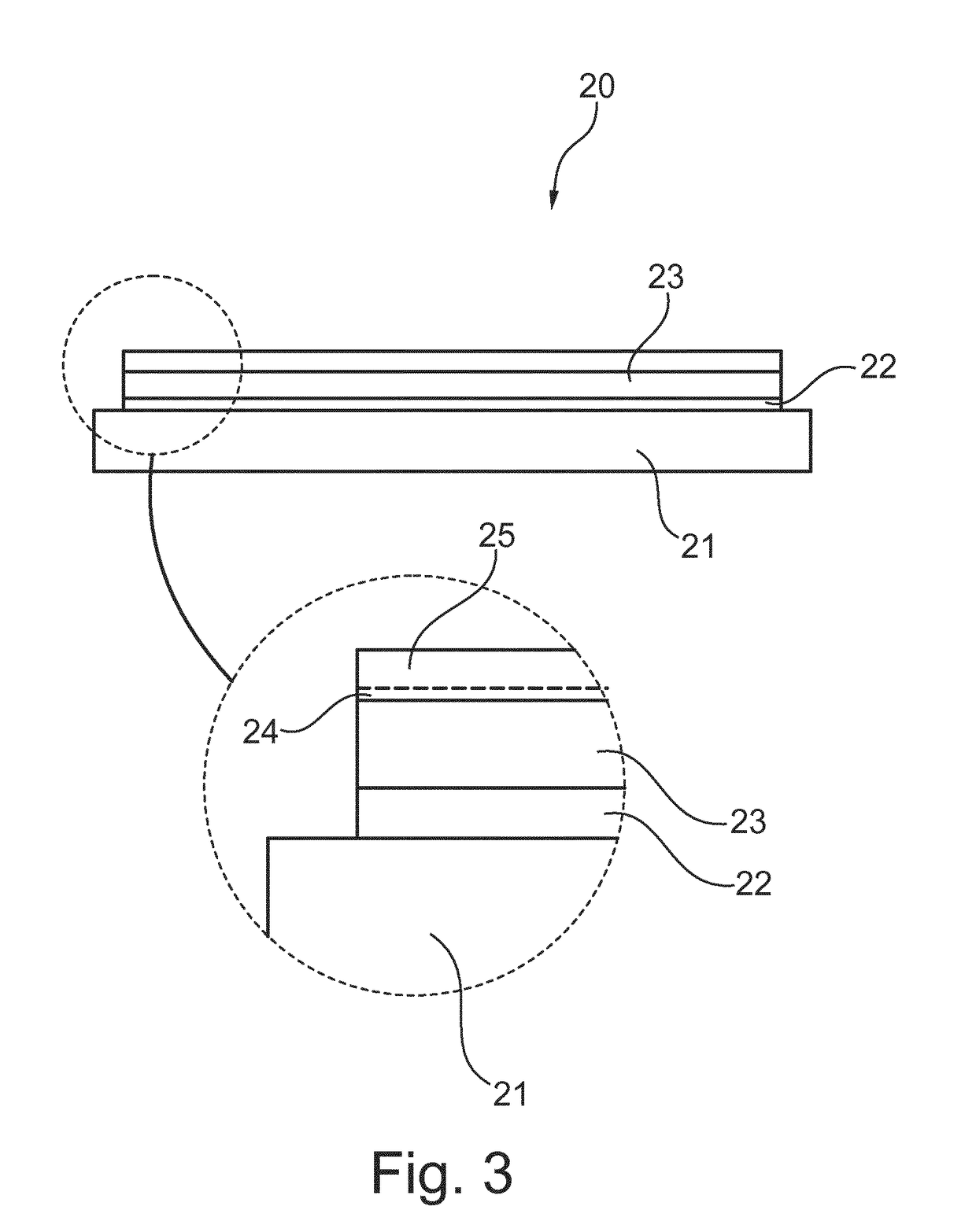
[0059]FIG. 3 shows an embodiment 20 of an organic light emitting diode (OLED). This OLED 20 has a substrate layer 21, like a glass layer. A first conductive layer 22 is deposited with a conventional physical vapor deposition method on this substrate layer 21. Then an emissive electroluminescent layer 23 is provided on top of the conductive layer 22.

[0060]With the method according to the invention a second conductive layer 24, 25 is arranged on top of the sensitive, emissive electroluminescent layer 23. The first layer 24 of transparent conductive material is first deposited, after which the second layer 25 of transparent conductive material is deposited. Because both layers 24, 25 are subsequently deposited, a homogeneous layer is provide on the emissive electroluminescent layer 23.

[0061]When a voltage is applied to the two conductive layers 22 and 24, 25 the emissive electroluminescent layer 23 will emit light. As both conductive layers can be made transparent using for example ind...


PUM

PropertyMeasurementUnit
Transparencyaaaaaaaaaa
Velocityaaaaaaaaaa

Abstract

The invention relates to a method for depositing a target material onto an organic electrically functional material. The method includes the steps of: providing a substrate with an organic electrically functional material, like an emissive electroluminescent layer; creating a vapor plume of target material by pulsed laser deposition; depositing a first layer of target material on the organic electrically functional material, while maintaining the maximum particle velocity of the deposited particles below a preset value; and depositing a second layer of target material on the first layer of target material, while the maximum particle velocity of the deposited particles is above the preset value. The invention also relates to an intermediate product and to an organic light emitting diode.

Description

CROSS-REFERENCE TO RELATED APPLICATIONS[0001]This application is the United States national phase of International Application No. PCT / EP2013 / 071429 filed Oct. 14, 2013, and claims priority to European Patent Application No. 12188835.8 filed Oct. 17, 2012, the disclosures of which are hereby incorporated in their entirety by reference.BACKGROUND OF THE INVENTIONField of the Invention[0002]The invention relates to a method for depositing a target material onto an organic electrically functional material.Description of Related Art[0003]Depositing methods, and in particular physical vapor deposition methods, use a plume of vapor with particles, which are bombarded onto a substrate material. This plume of vapor is generated by exciting a target material, for instance using ions or photons, such that particles are freed from the target material. Due to the excitement, the particles gain kinetic energy, which moves the particles to the substrate and which energy is used for the particles ...

Claims


Application Information

Patent Timeline
IPC IPC(8): H01L51/56H01L51/00C23C14/08C23C14/28C23C14/34C23C14/02H01L51/52H01L51/50
CPCH01L51/56C23C14/024C23C14/086C23C14/28C23C14/3485H01L51/0021H01L51/5012H01L51/5206H01L51/5234C23C14/3492H01L2251/5369H01L2251/308H10K71/00H10K50/11H10K50/81H10K50/828H10K71/60H10K2102/103H10K2102/331
Inventor DEKKERS, JAN MATTHIJNJANSSENS, JAN ARNAUD
Owner LAM RES CORP
Why Eureka
Try Eureka