Light source system and projection system

a technology of projection system and light source, applied in the field of projection technology, can solve the problems of reducing and achieve the effect of increasing the utilization efficiency of compensation lights and reducing scattering loss of compensation lights

Active Publication Date: 2018-11-27
APPOTRONICS CORP LTD
View PDF20 Cites 3 Cited by
  • Summary
  • Abstract
  • Description
  • Claims
  • Application Information

AI Technical Summary

Benefits of technology

[0006]To solve this problem, it has been proposed to use laser sources as compensation light sources for two chip DMD projection systems, to make the color coordinates of the red and green lights closer to the standard color gamut. For example, when a red laser light is used as a compensation light, the red laser light and blue laser light are both incident on the yellow phosphor material; because the red laser light cannot excite the yellow phosphor, a mixed light of blue light, yellow light and red laser light is generated. This way, the red laser light compensates for the color gamut of the red light, so that the color coordinates of the red light are closer to the standard color gamut. However, when the red laser or other compensation lights are incident on the phosphor material, the compensation lights are scattered by the phosphor material and some of them is lost, which reduced the utilization efficiency of the compensation lights.
[0007]Accordingly, the present invention is directed to a light source system and projection system that solves the problem of low utilization efficiency of the compensation light in the conventional technology.
[0032]Compared to conventional technology, embodiments of the present invention have the following advantages:
[0033]In the light source system and projection system of the embodiments, the rotating color wheel includes a first region and a second region, the first region generates a sequence of light containing at least two different colors when illuminated by the excitation light, and the second region transmits the compensation lights. This allows the compensation lights and the light of different colors to be combined to form projected image. The compensation lights are not illuminated on the phosphor, but are directly transmitted, so that the scattering loss of the compensation lights is reduced, and the utilization efficiency of the compensation lights is increased.

Problems solved by technology

However, when the red laser or other compensation lights are incident on the phosphor material, the compensation lights are scattered by the phosphor material and some of them is lost, which reduced the utilization efficiency of the compensation lights.

Method used


Image

  • Light source system and projection system
  • Light source system and projection system
  • Light source system and projection system

Examples


first embodiment

[0051

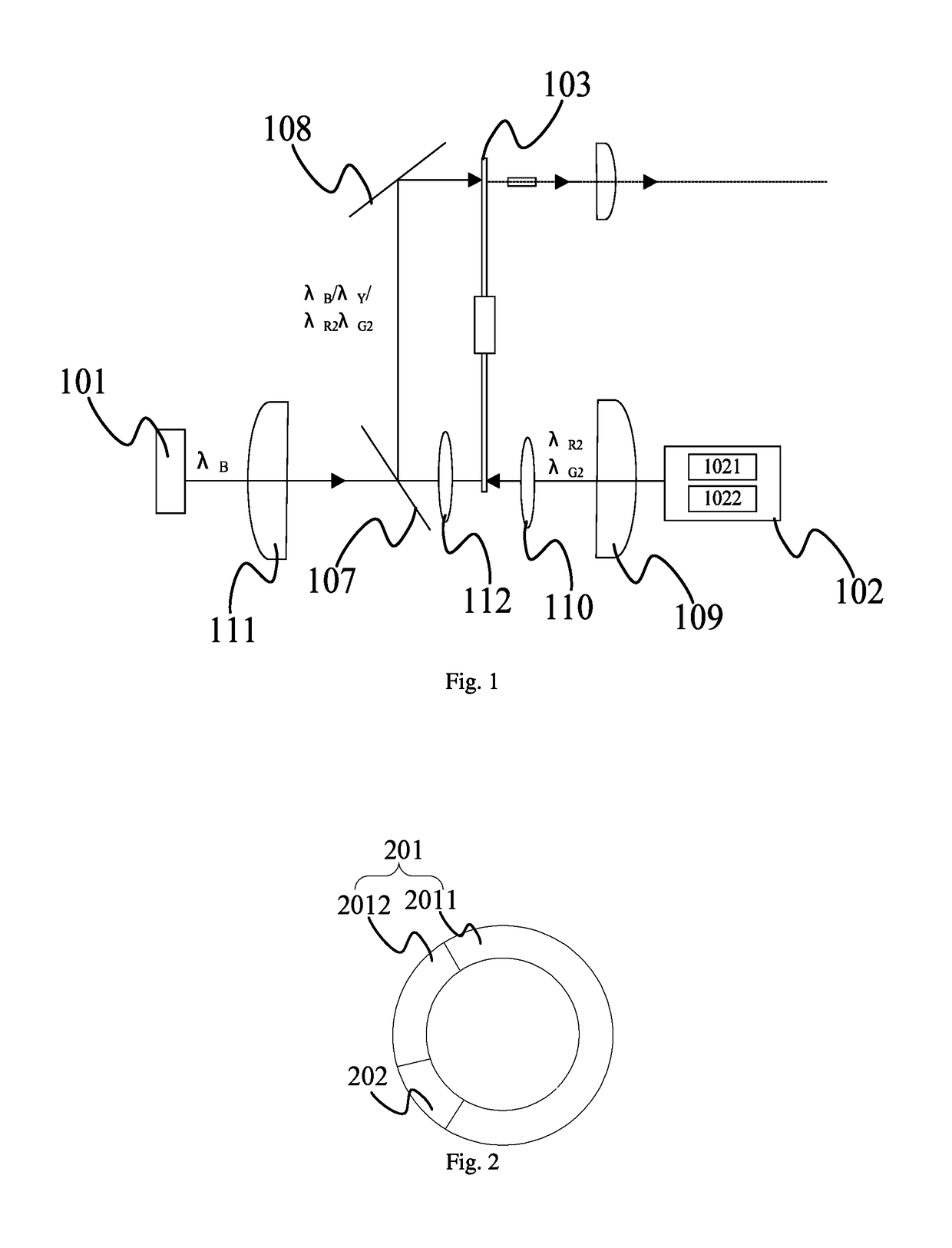
[0052]This embodiment provides a light source system. As shown in FIG. 1, the light source system includes an excitation light source 101, a compensation light source 102, and a rotating color wheel 103. The excitation light source 101 is preferably a semiconductor laser that emits a blue light of a wavelength of 445 nm. The excitation light source 101 emits an excitation light during at least first time intervals and second time intervals, and the compensation light source 102 emits a compensation light during at least third time intervals. The compensation light includes at least one color laser light. The rotating color wheel 103 includes at least a first region and a second region. During the first time intervals and the second time intervals, the first region is illuminated by the excitation light and sequentially generates a light containing at least two color components; during at least the third time intervals, the second region transmits the compensation light. The lig...

second embodiment

[0059

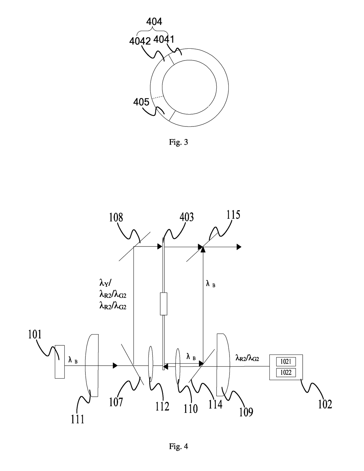
[0060]This embodiment provides a light source system. The light source system of this embodiment is similar to that of the first embodiment, with the following differences. In this embodiment, the rotating color wheel 403, as shown in FIG. 3, includes a first region 404 and a second region 405; the first region 404 includes phosphor segment 4041 and transparent segment 4042. During the first time intervals, the phosphor segment 4041 is illuminated by the excitation light to generate a yellow light. During the second time intervals, the transparent segment 4042 transmits the excitation light and the first compensation light, or, during the second time intervals, the transparent segment 4042 transmits the excitation light and the second compensation light. During the third time intervals, the second region 405 transmits the first compensation light and the second compensation light. More specifically, the phosphor segment 4041 is a segment that carries a yellow phosphor material;...

third embodiment

[0066

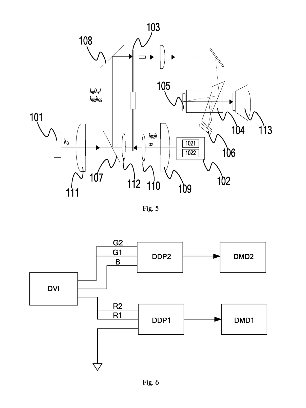
[0067]This embodiment provides a projection system. As shown in FIG. 5, the projection system includes an excitation light source 101, a compensation light source 102, a rotating color wheel 103, a light division system 104, a first light modulator 105 and a second light modulator 106. The excitation light source 101 is preferably a semiconductor laser that emits a blue light of a wavelength of 445 nm. The excitation light source 101 emits an excitation light during at least first time intervals and second time intervals, and the compensation light source 102 emits a compensation light during at least third time intervals. The rotating color wheel 103 includes at least a first region and a second region. During the first time intervals and the second time intervals, the first region is illuminated by the excitation light and sequentially generates a light containing at least two different color components; during at least the third time intervals, the second region transmits th...


PUM


Abstract

A light source system includes an excitation light source emitting excitation light in at least first and second time intervals; a compensation light source emitting compensation light in at least third time intervals, the compensation light including laser light of at least one color; and a rotating color wheel, including at least first and second regions, the first region generating light of at least two different colors in time sequence under irradiation of the excitation light in the first and second time sequences, and the second region transmitting the compensation light in at least the third time sequence. The light of the at least two different colors includes at least one type of wide-spectrum fluorescence, and the laser compensates for the fluorescence or light split from the fluorescence. The compensation light is directly transmitted without being irradiated upon fluorescent powder, so scattering loss of the compensation light is reduced.

Description

BACKGROUND OF THE INVENTION[0001]Field of the Invention[0002]This invention relates to projection technology, and in particular, it relates to a light source system and projection system.[0003]Description of Related Art[0004]DLP (digital light processing) projection technology uses DMD (digital micromirror device) to achieve display of visible digital information. Current DLP projection system typically uses a single chip DMD or three chip DMD. But because two chip DMD projection system has the advantage of both higher light efficiency and lower cost, they are gaining wider use now.SUMMARY[0005]Current two chip DMD projection system typically uses a blue laser light to excite a yellow phosphor powder to generate a sequence of blue light and yellow light, and then use a light division and combination prism to divide the yellow light into green light and red light, thereby obtaining the three primary colors of red, green and blue for projection. However, because the green and red ligh...

Claims


Application Information

Patent Timeline
Patent Type & Authority Patents(United States)
IPC IPC(8): G03B21/00G03B21/20H04N9/31
CPCG03B21/008G03B21/20H04N9/3161H04N9/3158G03B21/204G03B33/08
Inventor GUO, ZUQIANGWANG, ZEQINHU, FEI
Owner APPOTRONICS CORP LTD
Why Eureka
Try Eureka