Welding machine and control method therefor

a welding machine and control method technology, applied in the field of welding machines, can solve the problems of individual product shape errors, and achieve the effect of accurate welding position correction

Active Publication Date: 2019-01-29
AMADA HLDG CO LTD
View PDF25 Cites 7 Cited by
  • Summary
  • Abstract
  • Description
  • Claims
  • Application Information

AI Technical Summary

Benefits of technology

[0006]It is an object of embodiments to provide a welding machine capable of welding the individual products, while accurately correcting the welding positions even when the products have shape errors, and to provide a control method therefor.
[0015]In accordance with the welding machine and the control method therefor according to the embodiments, even when the products have shape errors, the individual products can be welded while accurately correcting the welding positions.

Problems solved by technology

However, each individual of the products has a shape error caused by distortion and the like at the time of bending, or the time of assembly.

Method used


Image

  • Welding machine and control method therefor
  • Welding machine and control method therefor
  • Welding machine and control method therefor

Examples


Embodiment Construction

[0039]A description is made below of a welding machine according to the embodiment and a control method therefor with reference to the accompanying drawings. The welding machine according to the embodiment is, as an example, a laser welding machine that welds a product by a laser beam. The welding machine is not limited to the laser welding machine.

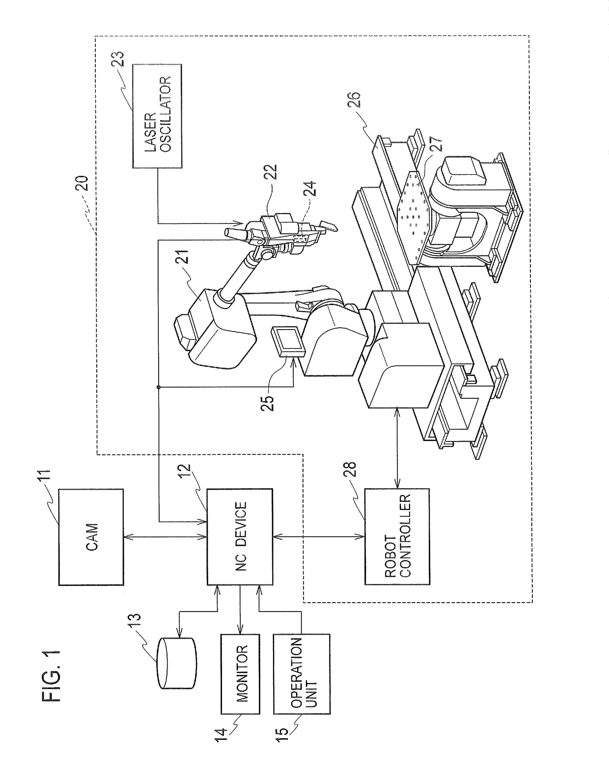
[0040]First, by using FIG. 1, a description is made of an entire configuration example of the laser welding machine. In FIG. 1, the CAM 11, the storage unit 13, the monitor 14, the operation unit 15, and the welding robot 20 are connected to the NC device 12.

[0041]The operation unit 15 may be a touch panel provided on the screen of the monitor 14. The operation unit 15 may be, for example, an operation unit, which is separate from the monitor 14 and includes a keyboard and a mouse.

[0042]The CAM 11 generates a processing program for use in the event of welding the product as a welding target by the welding robot 20. It is also possible to ...


PUM

PropertyMeasurementUnit
shape errorsaaaaaaaaaa
shape erroraaaaaaaaaa
constant surface coordinatesaaaaaaaaaa

Abstract

An edge extraction unit extracts an edge image from a photographed image obtained by photographing a product with a camera. A constant edge acquisition unit acquires, as a constant edge image, an edge image in a constant surface where a positional deviation does not occur with respect to a welding point set by a processing program, the acquired image belonging to the extracted edge image. A correction amount acquisition unit performs pattern-matching between a master constant edge image and a workpiece edge image, which are acquired by the constant edge acquisition unit, and acquires a deviation amount between both thereof as a correction amount with respect to the welding point. A processing program correction unit corrects the welding point by the correction amount, and generates a corrected processing program for welding the workpiece. A welding robot welds the workpiece based on the corrected processing program.

Description

TECHNICAL FIELD[0001]The present disclosure relates to a welding machine that welds a product as a welding target, and to a control method therefor.BACKGROUND ART[0002]In the case of welding a plurality of the same products by a welding machine, welding positions of the products are photographed with a camera, and the welding positions are corrected, based on the photographed images (refer to Patent Literature 1).[0003]One of the plurality of products is referred to as a master serving as a reference, and the other products are referred to as workpieces. In Patent Literature 1, in the event of correcting the welding positions, edge images (outline images) of the products are used. By using the edge images, even when the products have stains, scratches, diffusion and the like, pattern-matching between an image of the master and images of the workpieces is performed without being influenced by these stains, scratches, diffusion and the like to a large extent, thus making it possible t...

Claims


Application Information

Patent Timeline
Patent Type & Authority Patents(United States)
IPC IPC(8): B23K26/02B23K26/21B23K26/04G05B19/402B23K26/042G05B19/408B25J9/16G06T7/00B23K26/03G06T7/13
CPCG05B19/402B23K26/032B23K26/04B23K26/042B23K26/21B25J9/1684G05B19/4083G06T7/0004G06T7/13B23K26/02G06T2207/30164G05B2219/37563G05B2219/45104G05B2219/45138G05B2219/4705G06T2207/10004G06T2207/30136
Inventor INOUE, HIROKI
Owner AMADA HLDG CO LTD
Why Eureka
Try Eureka