Closed loop control of drilling toolface

a technology of drilling toolface and closed loop, which is applied in the direction of directional drilling, borehole/well accessories, surveying, etc., can solve the problems of directional drilling tools that exhibit tendencies to drill (or), and achieve the effect of reducing wellbore tortuosity and improving drilling efficiency and consistency

Active Publication Date: 2019-02-26
SCHLUMBERGER TECH CORP
View PDF37 Cites 5 Cited by
  • Summary
  • Abstract
  • Description
  • Claims
  • Application Information

AI Technical Summary

Benefits of technology

[0006]The disclosed embodiments may provide various technical advantages. For example, the disclosed embodiments provide for real-time closed loop control of the drilling toolface. As such, the disclosed methods may provide for improved well placement and reduced wellbore tortuosity. Moreover, by providing for closed loop control, the disclosed methods tend to improve drilling efficiency and consistency.

Problems solved by technology

One difficulty with automated drilling methods (and directional drilling methods in general) is that directional drilling tools exhibit tendencies to drill (or turn) in a direction offset from the set point direction.
Exacerbating this difficulty, these tendencies can be influenced by numerous factors and may change unexpectedly during a drilling operation.

Method used


Image

  • Closed loop control of drilling toolface
  • Closed loop control of drilling toolface
  • Closed loop control of drilling toolface

Examples


Embodiment Construction

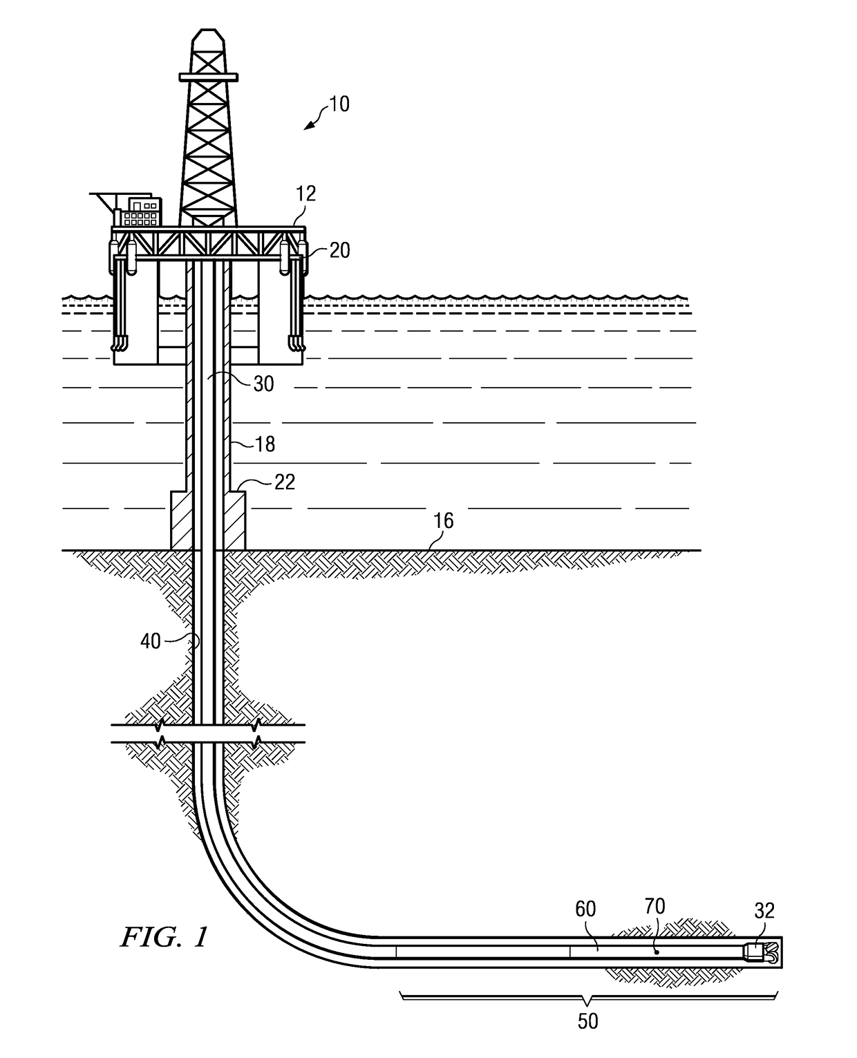
[0016]FIG. 1 depicts a drilling rig 10 suitable for using various method and system embodiments disclosed herein. A semisubmersible drilling platform 12 is positioned over an oil or gas formation (not shown) disposed below the sea floor 16. A subsea conduit 18 extends from deck 20 of platform 12 to a wellhead installation 22. The platform may include a derrick and a hoisting apparatus for raising and lowering a drill string 30, which, as shown, extends into borehole 40 and includes a bottom hole assembly (BHA) 50. The BHA 50 includes a drill bit 32, a steering tool 60 (also referred to as a directional drilling tool), and one or more downhole navigation sensors 70 such as measurement while drilling sensors including three axis accelerometers and / or three axis magnetometers. The BHA 50 may further include substantially any other suitable downhole tools such as a downhole drilling motor, a downhole telemetry system, a reaming tool, and the like. The disclosed embodiments are not limit...


PUM


Abstract

A downhole closed loop method for controlling a drilling toolface includes measuring first and second attitudes of the subterranean borehole at corresponding first and second upper and lower survey stations. The first and second attitudes are processed downhole while drilling to compute an angle change of the subterranean borehole between the upper and lower survey stations. The computed angle change is compared with a predetermined threshold. This process may be continuously repeated while the angle change is less than the threshold. The first and second attitudes are further processed downhole to compute a toolface angle when the angle change of the subterranean borehole is greater than or equal to the threshold. The toolface angle may then be further processed to control a direction of drilling of the subterranean borehole.

Description

FIELD OF THE INVENTION[0001]Disclosed embodiments relate generally to methods for maintaining directional control during downhole directional drilling operations and more particularly to method for determining a downhole toolface offset while drilling.BACKGROUND INFORMATION[0002]The use of automated drilling methods is becoming increasingly common in drilling subterranean wellbores. Such methods may be employed, for example, to control the direction of drilling based on various downhole feedback measurements, such as inclination and azimuth measurements made while drilling or logging while drilling measurements.[0003]One difficulty with automated drilling methods (and directional drilling methods in general) is that directional drilling tools exhibit tendencies to drill (or turn) in a direction offset from the set point direction. For example, when set to drill a horizontal well straight ahead, certain drilling tools may have a tendency to drop inclination (turn downward) and / or to ...

Claims


Application Information

Patent Timeline
Patent Type & Authority Patents(United States)
IPC IPC(8): E21B45/00E21B7/06E21B47/12E21B47/022
CPCE21B7/06E21B45/00E21B47/022E21B47/124E21B7/04E21B44/005E21B47/26
Inventor HORNBLOWER, PETERBOGATH, CHRISTOPHER C.BOWLER, ADAMSUGIURA, JUNICHI
Owner SCHLUMBERGER TECH CORP
Why Eureka
Try Eureka