
Optical fiber rod, optical fiber, image fiber, and method for manufacturing optical fiber rod

a technology of optical fiber and optical fiber rod, which is applied in the direction of manufacturing tools, cladding optical fiber, instruments, etc., can solve the problems of reducing the adhesion between reducing the adhesion of the core and the cladding, and reducing the optical transmission loss. , to achieve the effect of small optical transmission loss and large refractive index

Active Publication Date: 2019-02-26
KURARAY CO LTD
View PDF18 Cites 1 Cited by
  • Summary
  • Abstract
  • Description
  • Claims
  • Application Information

AI Technical Summary

Benefits of technology

The solution achieves a large refractive index difference between the core and cladding while minimizing optical transmission loss, improving the optical performance of the fiber by maintaining good adhesion and reducing interfacial debonding.

Problems solved by technology

However, when the core diameter is several μm or less, the optical transmission loss of a plastic optical fiber is large, which presents a problem.
Causes for such degradation of the transmission loss include a decrease in adhesion between the core and the cladding, and the interfacial structure mismatch between the core and the cladding.

Method used


Image

  • Optical fiber rod, optical fiber, image fiber, and method for manufacturing optical fiber rod
  • Optical fiber rod, optical fiber, image fiber, and method for manufacturing optical fiber rod
  • Optical fiber rod, optical fiber, image fiber, and method for manufacturing optical fiber rod

Examples


first embodiment

[First Embodiment]

[0029]Embodiments of the present invention are described hereinafter with reference to the drawings.

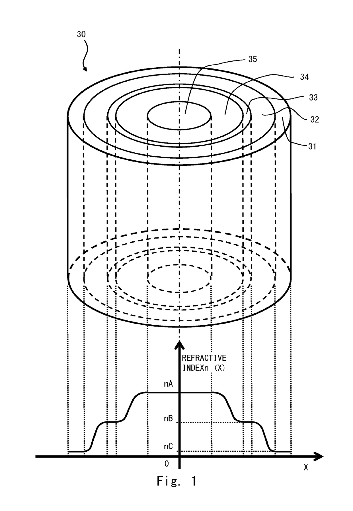
[0030]FIG. 1 is a view showing an example of the structure and the refractive index of each region of an optical fiber rod 30 according to this embodiment. The measurements shown in FIG. 1 do not always coincide with the scale of the rod 30 according to this embodiment. As shown in FIG. 1, the optical fiber rod 30 according to this embodiment includes a center region 35, a first copolymer region 34, an intermediate region 33, a second copolymer region 32, and an outer region 31.

[0031]The refractive index decreases in the order: the center region 35>the first copolymer region 34>the intermediate region 33>the second copolymer region 32>the outer region 31. The refractive index of the center region 35, the intermediate region 33 and the outer region 31 is uniform in each region. On the other hand, the refractive index of the first copolymer region 34 and the second cop...

example 1

[0085]A glass cylindrical container (with an inside diameter of 100 mm) was placed horizontally in an air thermostat bath at a temperature of 70° C. The cylindrical container rotated (500 turns per minute). The rotational axis and the central axis of the cylindrical container coincided. Under such conditions, a mixture was injected through an inlet at one end of the cylindrical container in the length direction. This mixture was a mixture of a polymerization initiator, a chain transfer agent for molecular weight regulation, and a low refractive index monomer (2,2,3,3-tetrafluoropropyl methacrylate: the refractive index of the polymer was 1.422).

[0086]The rate of injection of the mixture was adjusted so that the rate of deposition of a polymer was 1 mm per hour. After injection, the cylindrical container continued to rotate for three hours. After that, heating (at a temperature of 120° C. for three hours) was done. As a result, the outer region 31 made of a polymer produced only from...


PUM

PropertyMeasurementUnit
diameteraaaaaaaaaa
diameteraaaaaaaaaa
diameteraaaaaaaaaa

Abstract

An optical fiber rod (30) according to the present invention includes a center region (35), an outer region (31) formed around the center region (35), and an intermediate region (33) formed between the center region (35) and the outer region (31), and satisfies nA>nB>nC where nA is the refractive index of a material A produced by polymerization of a monomer ma, nB is the refractive index of a material B produced by polymerization of a monomer mb, and nC is the refractive index of a material C produced by polymerization of a monomer mc. The center region (35) is made of a material produced by polymerization of a monomer mixture containing the monomer ma, the outer region (31) is made of a material produced by polymerization of a monomer mixture containing the monomer mc, and the intermediate region (33) is made of a material produced by polymerization of a monomer mixture containing the monomer mb. The refractive index decreases in the order: the center region (35)>the intermediate region (33)>the outer region (31).

Description

TECHNICAL FIELD[0001]The present invention relates to an optical fiber rod, an optical fiber, an image fiber, and a method for manufacturing an optical fiber rod.BACKGROUND ART[0002]Image fibers are widely used in the industrial field and the medical field. An image fiber has a structure in which a plurality of optical fibers are packed into a bundle and, in general, claddings of the optical fibers are fused so that a plurality of cores are formed in the cladding (see Patent Literature 4). The number of pixels (number of cores) of an image fiber is 1000 or more, for example, and not a few image fibers have 2000 to several tens of thousands of cores. The outside diameter of an image fiber is generally several mm or less. Therefore, the diameter of the core in an image fiber is on the order of μm.[0003]A material used to form an image fiber is glass (see Patent Literature 1) or plastic (see Patent Literature 2). A plastic image fiber is more flexible than a glass image fiber. An examp...

Claims


Application Information

Patent Timeline
Patent Type & Authority Patents(United States)
IPC IPC(8): G02B6/028B29D11/00G02B6/04G02B6/02C03B37/012G02B6/036C08F2/44C08F265/04
CPCG02B6/0288B29D11/00682C03B37/01214G02B6/02G02B6/02038G02B6/036G02B6/03633G02B6/04G02B6/0283C08F265/04C03B2201/08C08F2/44
Inventor IWAKAWA, RYUICHI
Owner KURARAY CO LTD
Learn More