
Solid electrolytic capacitor element, solid electrolytic capacitor, method for producing solid electrolytic capacitor element, and method for producing solid capacitor

a technology of solid electrolytic capacitor and solid electrolytic capacitor, which is applied in the direction of electrolytic capacitor, capacitor details, capacitor manufacture, etc., can solve the problem of large leak current and achieve the effect of less leak curren

Active Publication Date: 2019-03-12
MURATA MFG CO LTD
View PDF18 Cites 0 Cited by
  • Summary
  • Abstract
  • Description
  • Claims
  • Application Information

AI Technical Summary

Benefits of technology

[0015]The silane coupling agent, the metal chelating agent, and the wetting agent can all impart sufficient hydrophilicity to the masking member.
[0017]These silane coupling agents can impart sufficient hydrophilicity to the surface of the masking member.
[0019]These metal chelating agents can impart sufficient hydrophilicity to the surface of the masking member.
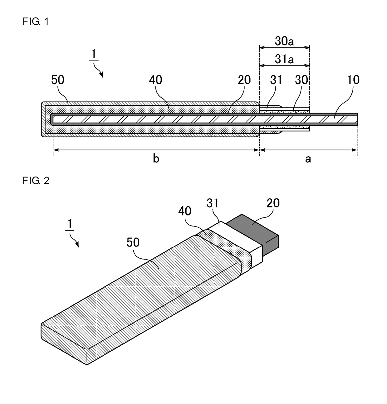
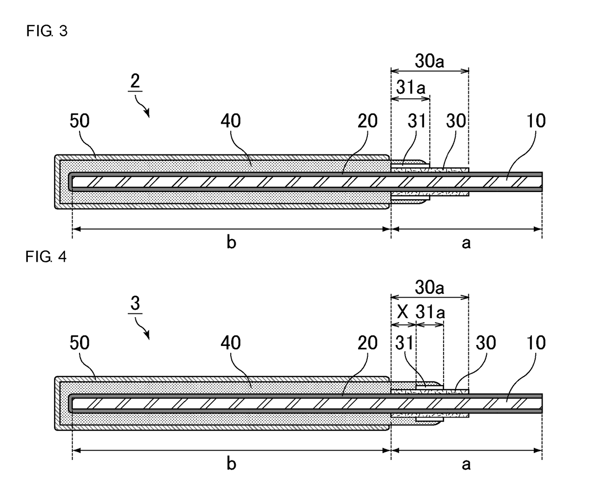
[0027]According to this method, since a hydrophilic member is formed on a surface of the masking member, a raw material solution or dispersion of a conductive polymer for forming the solid electrolyte layer is easily retained on the hydrophilic member. Thus, no gap is formed between the masking member and the solid electrolyte layer. As a result, a solid electrolytic capacitor element with less leak current can be produced.

Problems solved by technology

However, typical solid electrolytic capacitors such as one disclosed in Japanese Unexamined Patent Application Publication No. 2009-158692 sometimes have an issue of large leak current.

Method used


Image

  • Solid electrolytic capacitor element, solid electrolytic capacitor, method for producing solid electrolytic capacitor element, and method for producing solid capacitor
  • Solid electrolytic capacitor element, solid electrolytic capacitor, method for producing solid electrolytic capacitor element, and method for producing solid capacitor
  • Solid electrolytic capacitor element, solid electrolytic capacitor, method for producing solid electrolytic capacitor element, and method for producing solid capacitor

Examples


example 1

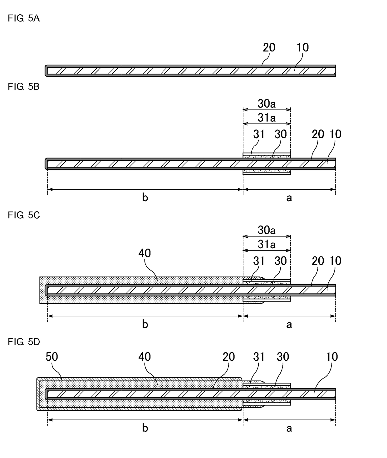
[0108]First, a chemically converted aluminum foil having a porous layer on its surfaces was prepared as a valve metal substrate, and cut into a predetermined shape.

[0109]Next, the masking member was applied to have a strip shape at a position a particular distance away from one end of the chemically converted aluminum foil in the long axis direction so that the masking member extended all around the chemically converted aluminum foil. As a result, the masking member penetrated the porous layer and formed the masking region. In the chemically converted aluminum foil divided by the masking region, the region that contained the small-area portion and the masking region was assumed to be the anode terminal region, and the region other than this region was assumed to be the cathode-forming region. A polyimide was used as the material for the masking member.

[0110]The masking region had a width of 0.7 mm and a height of 10 μm.

[0111]The chemically converted aluminum foil having the masking ...

example 2

[0116]Capacitor elements were prepared as in Example 1 except that the silane coupling agent was changed to 3-aminopropyltrimethoxysilane. As a result, a solid electrolytic capacitor of Example 2 was obtained.

example 3

[0117]Capacitor elements were prepared as in Example 1 except that the silane coupling agent was changed to a metal chelating agent, 8-quinolinol. As a result, a solid electrolytic capacitor of Example 3 was obtained.


PUM

PropertyMeasurementUnit
heightaaaaaaaaaa
thicknessaaaaaaaaaa
thicknessaaaaaaaaaa

Abstract

A solid electrolytic capacitor element that includes a valve metal substrate that has an anode terminal region and a cathode-forming region; a dielectric layer on the cathode-forming region; a solid electrolyte layer on the dielectric layer; a current collector layer on the solid electrolyte layer; a masking member on the anode terminal region, the masking member partitioning between the anode terminal region and the cathode-forming region and insulating the valve metal substrate from opposite polarity; and a hydrophilic member on a surface of the masking member.

Description

CROSS REFERENCE TO RELATED APPLICATIONS[0001]The present application claims priority to Japanese Patent Application No. 2016-164735, filed Aug. 25, 2016, the entire contents of which are incorporated herein by reference.BACKGROUND OF THE INVENTION[0002]Field of the Invention[0003]The present invention relates to a solid electrolytic capacitor element, a solid electrolytic capacitor, a method for producing a solid electrolytic capacitor element, and a method for producing a solid electrolytic capacitor.[0004]Description of the Related Art[0005]A solid electrolytic capacitor includes, for example, a solid electrolytic capacitor element prepared by forming an oxide coating film that constitutes a dielectric layer on a roughened surface of a valve metal substrate, forming a masking layer to separate an anode portion and a cathode portion from each other, and sequentially forming, on the dielectric layer outside the anode portion, a solid electrolyte layer, and a carbon paste layer and a...

Claims


Application Information

Patent Timeline
Patent Type & Authority Patents(United States)
IPC IPC(8): H01G9/15H01G9/012H01G9/042H01G9/025H01G9/00H01G9/10
CPCH01G9/15H01G9/0003H01G9/0036H01G9/025H01G9/0425H01G9/10H01G9/012H01G2009/0014H01G9/004H01G9/14H01G9/26
Inventor HARADA, HIROYUKI
Owner MURATA MFG CO LTD
Learn More