

Method and apparatus for thermal processing
a technology of thermal processing and apparatus, applied in lighting and heating apparatus, separation processes, combustion types, etc., can solve the problems of difficult processing, inability to allow just a single process to purify and restore water back to a usable commodity, and easy destruction of membranes by volatile organic compounds, etc., to achieve the effect of effectively and efficiently processing the majority of industrial waste water conditions
- Summary
- Abstract
- Description
- Claims
- Application Information
AI Technical Summary
Benefits of technology
Problems solved by technology
Method used
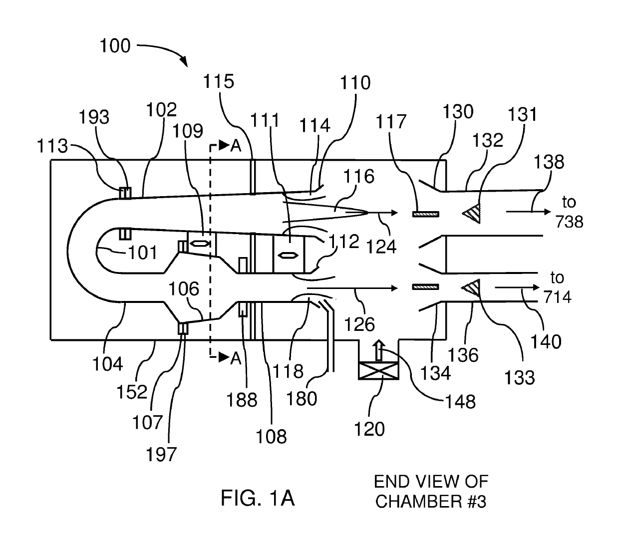
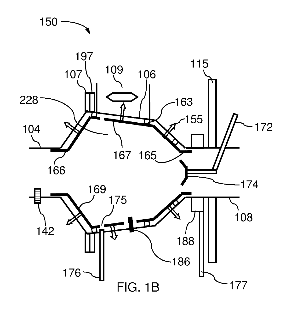
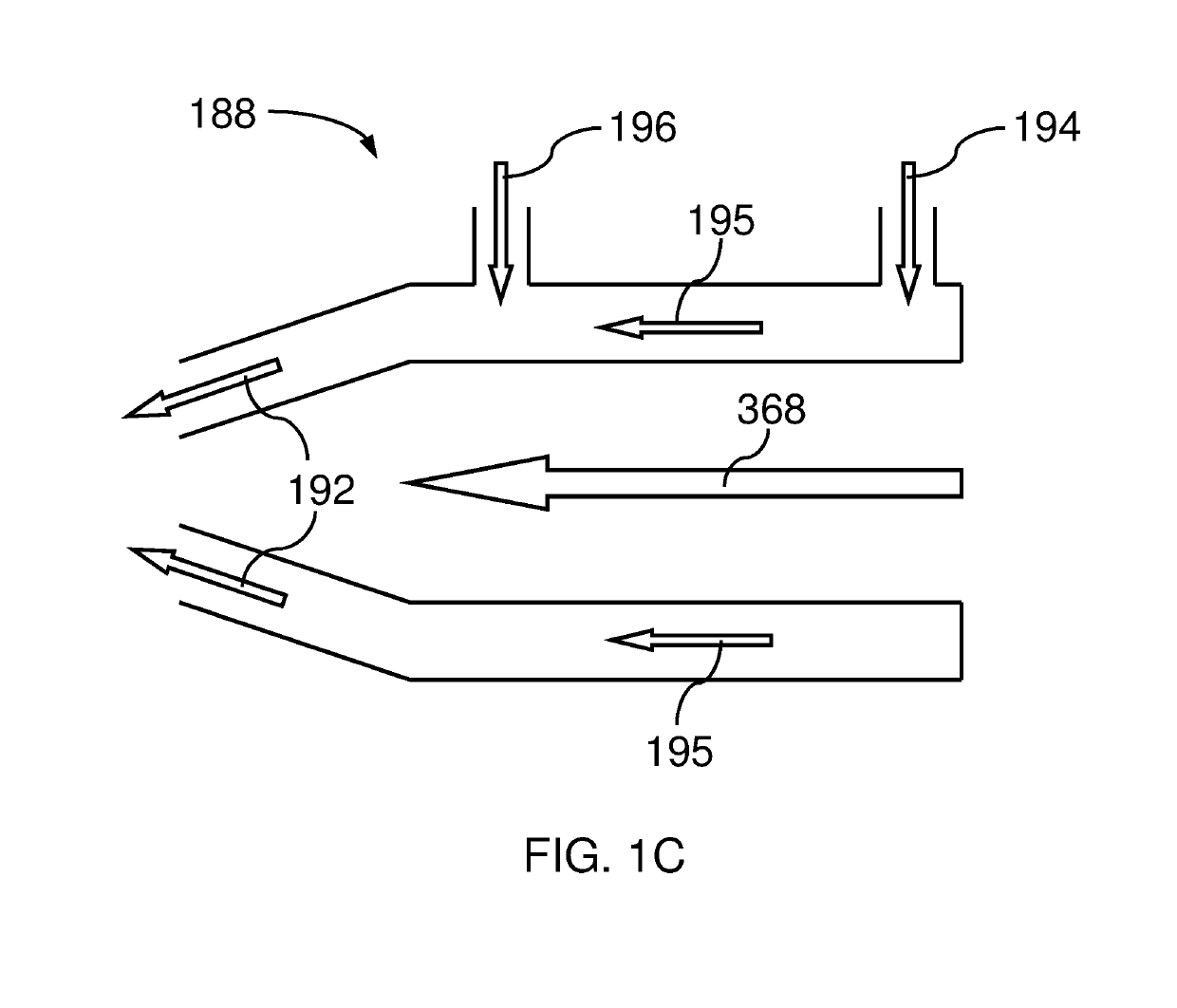
Image

Examples
Embodiment Construction
[0041]The subject apparatus and methods are described in the context of representative embodiments that are not intended to be limiting in any way.
[0042]In the following description, certain terms may be used such as “up”, “down”, “upper”, “lower”, “horizontal”, “vertical”, “left”, “right,” and the like. These terms are used, where applicable, to provide some clarity of description when dealing with relative relationships. But, these terms are not intended to imply absolute relationships, positions, and / or orientations. For example, with respect to an object, an “upper” surface can become a “lower” surface simply by turning the object over. Nevertheless, it is still the same object.
[0043]Embodiments of the invention can eliminate the need for injection wells and storage of contaminated materials, enabling responsible and technically affordable solutions. This will free future generations from the burden of a damaged and polluted environment. The correction and rehabilitation of the ...
PUM
 Abstract
Description
Claims
Application Information