Electronic detonator leakage current restriction

a technology of leakage current restriction and detonator, which is applied in the direction of electronic switching, blasting, electric devices, etc., can solve the problems of severe voltage starvation, short circuit of capacitors, and high current consumption, and achieve the effect of minimizing the effect of a problem blast hole and minimizing the effect of a leakage circui

Active Publication Date: 2019-04-23
DETNET SOUTH AFRICA (PTY) LTD
View PDF14 Cites 0 Cited by
  • Summary
  • Abstract
  • Description
  • Claims
  • Application Information

AI Technical Summary

Benefits of technology

[0027]Preferably in use, the current-limiting component is located outside a blast hole in which the respective detonator is positioned. This helps to reduce the likelihood that the current-limiting component would be damaged while the blast hole is being loaded.
[0028]It is possible to connect a respective current-limiting component in series in each wire of the down-hole harness to restrict the nature of a problem which would occur if one wire were to be inadvertently coupled to earth. Such coupling could result in an undesirable current flow if another part of the blasting system were to be earthed in some way.
[0031]It is within the scope of the invention to take current measurements over a period of time before a decision to disconnect is made. This makes the circuit insensitive to typical high start-up currents which may occur when a capacitor inside a detonator is discharged and the down-hole harness to the detonator is powered.
[0033]Preferably, though the current-limiting circuit is latching so that the down-hole harness remains disconnected from the bus until power is removed for a reasonable period. This approach minimises the effect of a problem blast hole on the remainder of the blast system although it is then not possible to fire the affected detonator.

Problems solved by technology

Although a tantalum capacitor performs well in this type of application it can suffer from a failure mode that could result in the capacitor short-circuiting.
This type of event can be catastrophic in a blasting system in which electronic detonators are connected in parallel to one another and are powered through a shared wire bus connected to a control device which may be some distance from a blast bench.
A short circuit in a capacitor, which is inside a detonator, results in a high current consumption and severe voltage starvation on a wire bus to which the detonator is connected.
This can reduce the voltage available for blasting which, in turn, can cause a misfire in the affected detonator and which can also cause other detonators in the blasting system to misfire.
Alternatively a significant time delay may be incurred while the faulty detonator is being identified and remedial action is taken.
The aforementioned problem is exacerbated if this type of failure only occurs once a supply voltage is raised to a level which is sufficiently high to supply blasting energy.
A delay of this type can result in significant financial losses.
There are other failures which can be detrimental to a parallel blasting circuit.
For example damage to the insulation of wires, that typically occurs when a detonator is loaded into a blast hole, can cause current leakage or a short-circuit.
A similar adverse effect can be produced by the ingress of a fluid into a detonator due to poor sealing between a crimp plug and a detonator tube, and similar factors.
A further concern is that a current leakage problem may not be apparent immediately when a detonator is loaded into a blast hole but may only appear after some time, possibly as wire to the detonator stretches during hole slumping, or due to a slow ingress of fluid into the detonator over time.
However, the disconnection of an entire chain of detonators is not helpful if the cause of the leakage problem lies in a single borehole.
U.S. Pat. No. 7,911,760 is similarly limited in that a remain chain of detonators is controlled via an actuator on a wire bus.
Although it is possible to modify systems of the aforementioned kind to isolate problem holes, the electronics required are relatively complex and can be expensive.
The effect of leakage current in a blasting system can be limited by decreasing the resistance of the bus wire so that the voltage drop across the bus wire due to a leakage current is limited.
These methods can however produce additional delays, particularly if problems are experienced only when a blasting voltage is applied to the bus wire.
This, however, can expose some detonators to a voltage which exceeds a rated operating voltage.

Method used


Image

  • Electronic detonator leakage current restriction
  • Electronic detonator leakage current restriction
  • Electronic detonator leakage current restriction

Examples


Embodiment Construction

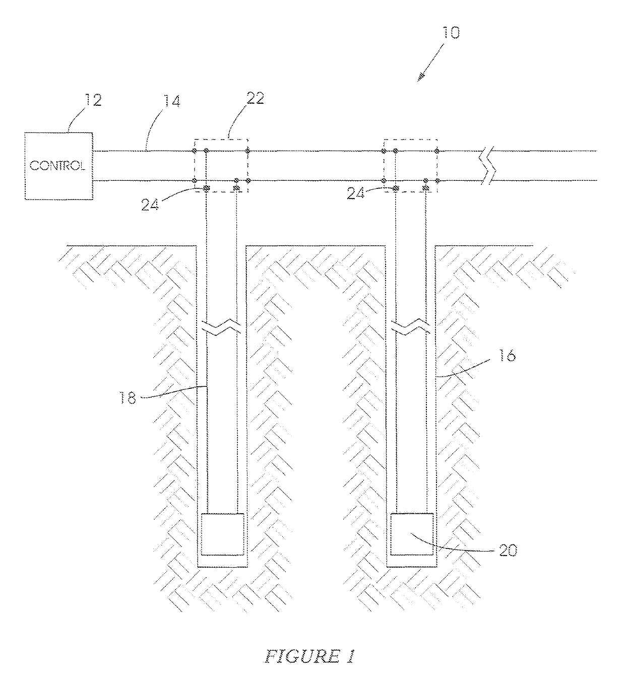
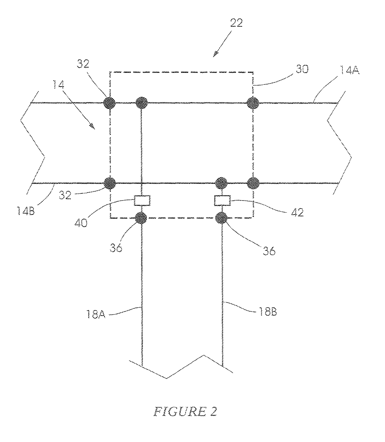
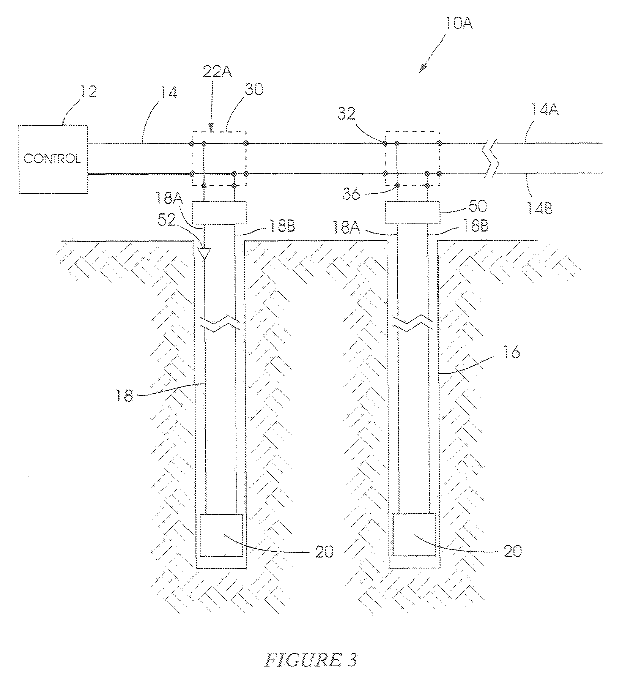
[0040]FIG. 1 of the accompanying drawings illustrates a blasting system 10 which includes a blasting control machine 12, an elongate wire bus 14 which typically is located on surface and which is connected to the machine 12, a plurality of boreholes or blast holes 16, a plurality of detonator down-hole harnesses 18, a plurality of electronic detonators 20 and a plurality of connectors 22. The connectors 22 are shown in FIG. 1 in dotted outline, for ease of reference and, similarly, in FIGS. 2 and 3.

[0041]Each connector 22 is used to make a respective connection between the bus 14 and an associated down-hole harness 18 which, in turn, is connected to a respective detonator 20. In this way the detonators are connected in parallel to each other via the bus 14.

[0042]Each detonator 20 includes electronic elements and, typically, a custom designed control circuit (ASIC) (not shown), all mounted inside a detonator can, as is known n the art.

[0043]Explosive material, not shown, placed in ea...


PUM


Abstract

A detonator system wherein a detonator is connected via a down-hole harness to a bus extending from a blast controller and wherein a component is connected in series with the down-hole harness to limit leakage current in the harness to a level which can be accommodated by the blast controller.

Description

CROSS-REFERENCE TO RELATED APPLICATIONS[0001]This application is a U.S. National Phase of International Patent Application No. PCT / ZA2015 / 000057, filed Sep. 1, 2015, which claims priority to ZA 2014 / 06453, filed Sep. 3, 2014, the entire contents of both of which are incorporated by referenced herein.BACKGROUND OF THE INVENTION[0002]This invention relates generally to an electronic blasting system and is particularly concerned with limiting the effects of undesirable leakage currents which may occur in the system.[0003]As used herein “leakage current” includes current flow in a blasting system that does not directly contribute to the effective operation of electronic detonators in the system.[0004]An electronic blasting system typically rakes use of a plurality of electronic detonators. Each detonator may include one or more capacitors which are used to ensure autonomous operation of the detonator if connecting wires to the detonator are broken, for example due to the effect of a bla...

Claims


Application Information

Patent Timeline
Patent Type & Authority Patents(United States)
IPC IPC(8): F42D1/055F42D1/04H03K17/08
CPCF42D1/055F42D1/043H03K17/08
Inventor SCHLENTER, CRAIG CHARLES
Owner DETNET SOUTH AFRICA (PTY) LTD
Why Eureka
Try Eureka