Monopole antenna

a technology of monopole antenna and antenna body, which is applied in the direction of antennas, antenna feed intermediates, basic electric elements, etc., can solve the problems of increased manufacturing cost, complicated configuration, and inconvenient helical structure, and achieve the effect of reducing the length of the physical circumferen

Inactive Publication Date: 2019-05-07
KIM MEE JEONG
View PDF11 Cites 1 Cited by
  • Summary
  • Abstract
  • Description
  • Claims
  • Application Information

AI Technical Summary

Benefits of technology

[0016]As described above, according to the monopole antenna of the present invention, an ultra-wideband antenna (UWB antenna) employing a quasi-Moebius strip and a via-hole structure can be miniaturized.
[0017]In other words, according to the present invention, a length of a physical circumference is reduced by 1 / (N+1) times as compared with a conventional ring antenna. While a resonance frequency is generated per one rotation around a circumference, the present invention can obtain an ultra-wideband characteristic ranging from about 2 GHz to 10 GHz by employing the quasi-Moebius strip and the via-hole.
[0018]In addition, according to the present invention, a radiation pattern in a far-field exhibits omni-directional characteristics similar to a typical monopole antenna, and directivity can be controlled by adjusting a rotation angle of each ring provided in a radiator.
[0019]Further, according to the present invention, the resonance frequency and a reflection coefficient are adjustable by varying three parameters of the quasi-Moebius strip, that is, a thickness of a ring line of the quasi-Moebius strip, a width of a bridge, and a radius and a position of the via-hole, and simulation results show that the quasi-Moebius strip having the via-hole structure can be applied to a matching network.
[0020]In addition, according to the present invention, the thickness of the ring line and a size and the position of the via-hole affect an inductance (L), and the width of the bridge and the size and position of the via-hole affect a capacitance (C), so that the three parameters of the quasi-Moebius strip can be applied to a matching circuit.
[0021]In other words, according to simulation and measurement results, the resonance frequency of a quasi-Moebius strip antenna is within a 2.4 GHz band, a peak value of a reflection coefficient S11 is 17.3 dB in the simulation result, and 27.65 dB in the measurement result.

Problems solved by technology

Among the above schemes, since a resonance frequency is generated per one rotation around a circumference, the helical structure is not suitable for a scheme of miniaturizing an antenna having a single resonance frequency characteristic.
In addition, schemes of applying the meta-material and the stacked structure have a disadvantage in that a configuration is complicated and a manufacturing cost is increased.
However, the above flat structure is not a perfect flat structure, and a line coupling effect occurs at a low frequency.

Method used


Image

  • Monopole antenna
  • Monopole antenna
  • Monopole antenna

Examples


Embodiment Construction

[0063]Hereinafter, a monopole antenna according to a preferred embodiment of the present invention will be described in detail with reference to the accompanying drawings.

[0064]1 Miniaturization of Monopole Antenna

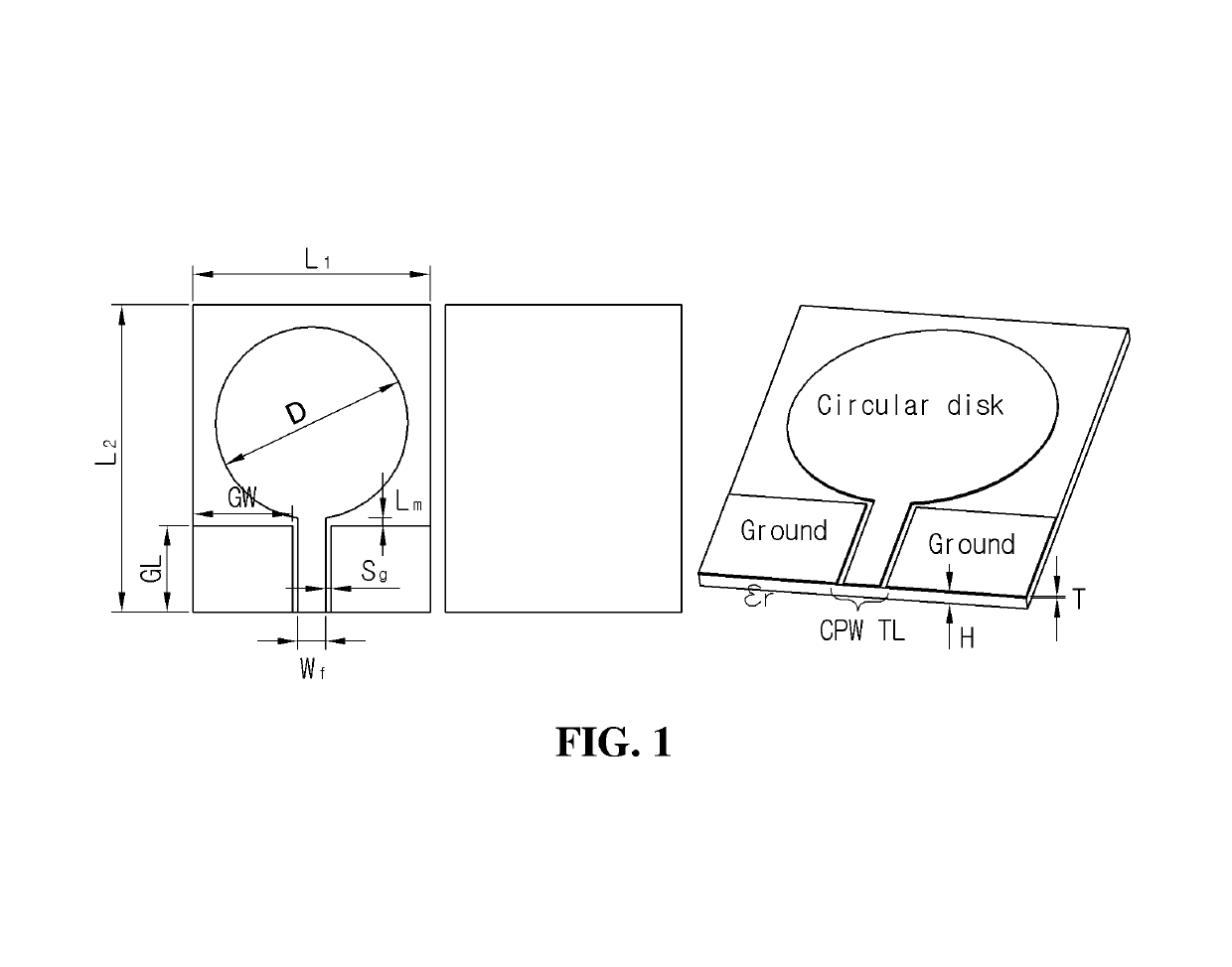
[0065]FIG. 1 is a block diagram showing a circular disc-shaped monopole antenna having a coplanar waveguide transmission line (hereinafter referred to as “CPW TL”) implemented on a dielectric substrate.

[0066]Electrical characteristics of the dielectric substrate are expressed by a dielectric constant εr of a dielectric, a dielectric thickness H, a copper foil thickness T, and a loss tangent value (tan δ). In this embodiment, the dielectric substrate a dielectric constant εr=2.2, a dielectric thickness H=30 mils (0.762 mm), a copper foil thickness T=0.5 oz. (0.018 mm), and a loss tangent value (tan δ)=0.001 (@ 5 GHz) is used.

[0067]In a coplanar waveguide line structure, as shown in FIG. 1, values of a slot width Sg and a center strip line width Wf are varied in a CPW TL fee...


PUM


Abstract

The present invention relates to a monopole antenna comprising: a radiator arranged in the center of a front surface of a dielectric substrate, and including a plurality of loops formed in a structure in which a Mobius strip is cut at least one time along the circumference; a first bridge for sequentially connecting one end of each loop; and a second bridge for connecting via-holes respectively formed at one end of the innermost loop and the outermost loop, thereby obtaining an effect of enabling an antenna, to which a quasi-Mobius strip and a via-hole structure are applied, to be miniaturized.

Description

TECHNICAL FIELD[0001]The present invention relates to a monopole antenna, and more particularly, to a monopole antenna applicable to a wireless communication system.BACKGROUND ART[0002]As wireless mobile communications evolve rapidly, various wireless communication systems such as 4G / 5G mobile communication terminals, wireless control systems, Machine to Machine (M2M), and Internet of Things (IoT) require elements which are more lightweight, have a simple structure, and are miniaturized into a structure that facilitates integration.[0003]Accordingly, various schemes for reducing a physical size of a circuit have been studied, and flat microwave elements and circuits have been widely developed and applied because they are easy to design and manufacture.[0004]In particular, manufacturers of mobile communication terminals and wireless control systems in the world require a miniaturized, flexible, broadband, high-gain antenna which is operated at a low power with high radiation efficien...

Claims


Application Information

Patent Timeline
Patent Type & Authority Patents(United States)
IPC IPC(8): H01Q1/38H01Q9/16H01Q7/00H01Q9/40H01Q3/01H01Q3/26
CPCH01Q1/38H01Q3/01H01Q9/40H01Q7/00H01Q9/16H01Q3/26H01Q1/36H01Q9/27H01Q21/28
Inventor KIM, MEE JEONG
Owner KIM MEE JEONG
Why Eureka
Try Eureka