
Binocular telescope with digital laser ranging function

a technology of laser ranging function and binocular telescope, which is applied in the field of optical instruments, can solve the problems of complex optical mechanical structure, difficult process, and inability to meet the requirements of actual mass production from the point of view of optical mechanical properties, and achieve the effect of simplifying the projection display component and no optical property loss

Active Publication Date: 2019-05-14
KUNMING SHUNHO OPTICS
View PDF4 Cites 7 Cited by
  • Summary
  • Abstract
  • Description
  • Claims
  • Application Information

AI Technical Summary

Benefits of technology

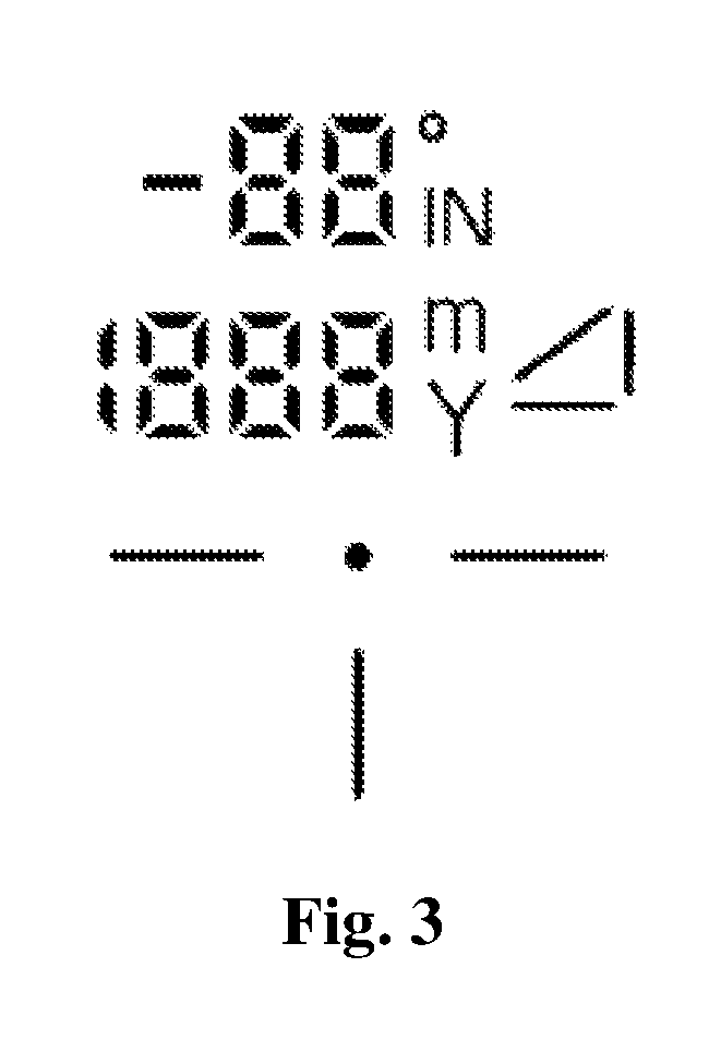
The invention is a binocular telescope that can be used for imaging and observing visible light while also processing other laser beams without interfering with the visible imaging light beam. The spatial structure features of the invention enable the seamless combination between the present invention and an electro-optic display device to form a binocular telescope with such functions as observation, laser ranging, and graphics and text information display, etc. The system is featured by compact structure, simple light path logic, and simple processing technology of parts. Additionally, the invention cancels a beam splitter plane and simplifies the projection display component using a transmission type display device (LCD or OLED), further forming a binocular telescope with laser ranging function.

Problems solved by technology

At present, the binocular telescope with laser ranging function has the problem that it cannot meet the requirements of actual mass production from the point view of optical mechanical properties.
The products with good performance have complex optical mechanical structure and difficult process, while the low-end products cannot meet the actual application requirements due to poor performance The erecting prism used by the binocular telescope with laser ranging function includes Porro prism, Schmidt-Pechan prism and Abbe prism.
By comparison, it is found that the Porro prism has slightly smaller qualified field of view and large space volume when the same material is used, so the final product is relatively bulky.
The Schmidt-Pechan prism is compact in size but has high light loss, and it is difficult to enlarge the aperture.
The structure is too complex after the beam splitter prism required for laser ranging is compounded, and changes in the shape such as back bulging caused by the required space result in an unsightly product.
However, its complex production process may result in high price.
Although the system can display the additional graphics and text information based on imaging principle of lens and beam splitter principle of prism plane, it still has two obvious insurmountable defects.
One is that the space provided by the prism to the display device is narrow, resulting in a small field of view, only one third of the field of view of the other light path.
For example, only a line of simple four-digit characters can be displayed, and a large field of view for display of graphics and text information cannot be achieved.
The other is that the beam splitting film is far from the normal incidence, resulting in a system transmittance of less than 35%, and the brightness of the displayed image is extremely low and the product cannot be used in the daytime.
Therefore, it is difficult to see the characters due to narrow space, simple structure, poor imaging quality, and unclear additional graphics and text information of the imaging lens group.

Method used


Image

  • Binocular telescope with digital laser ranging function
  • Binocular telescope with digital laser ranging function
  • Binocular telescope with digital laser ranging function

Examples


example 1

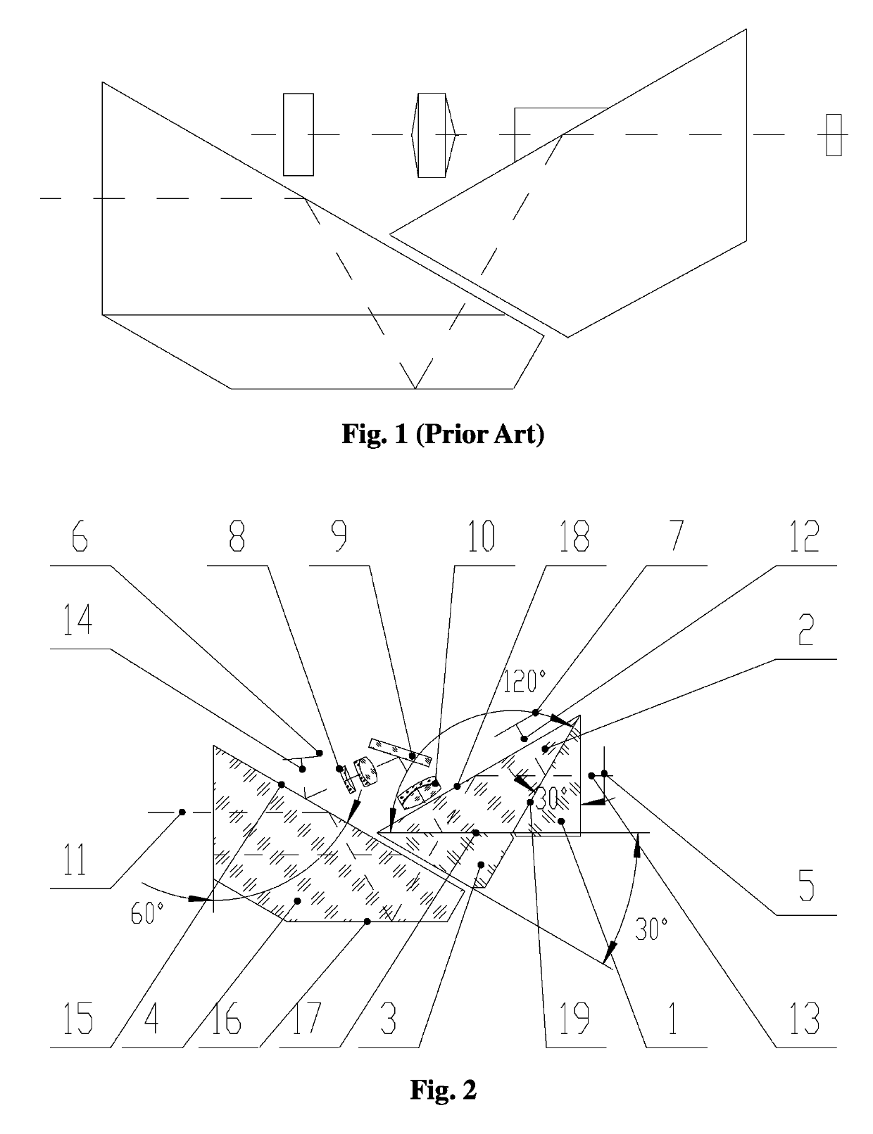
[0040]FIG. 1 to FIG. 5 show a binocular telescope with digital laser ranging function, comprising an objective component, a beam splitter and coincidence prism system and an ocular component; the beam splitter and coincidence prism system is arranged between the objective component and the ocular component;

[0041]The beam splitter and coincidence prism system comprises a roof prism 4 and a composite prism, the composite prism in one of two cylinders of the binocular telescope is composed of an isosceles prism 2, a right-angle prism A1 and a right-angle prism B3, wherein the right-angle prism A1 and the right-angle prism B3 have the same shape and symmetrically abut on the two isosceles planes of the isosceles prism 2; the composite prism in the other cylinder is composed of a right-angle prism A1 and a right-angle prism 25; wherein a right-angle plane 26 of the right-angle prism 25 is longer than the slope of the right-angle prism A1, and the right-angle plane 26 abuts on the slope o...

example 2

[0051]FIG. 6 to FIG. 7 show a binocular telescope with digital laser ranging function, comprising an objective component, a beam splitter and coincidence prism system and an ocular component; the beam splitter and coincidence prism system is arranged between the objective component and the ocular component;

[0052]the beam splitter and coincidence prism system comprises a roof prism 4 and a composite prism which is composed of the right-angle prism A1 and the right-angle prism 25; wherein the right-angle plane 26 of the right-angle prism 25 is longer than the slope of the right-angle prism A1, and the right-angle plane 26 abuts on the slope of the right-angle prism A1.

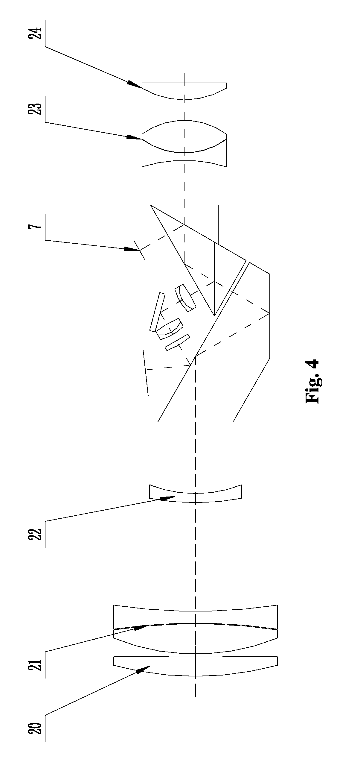
[0053]FIG. 7 is the structural diagram of the binocular telescope with simplified projection display component of the invention, and FIG. 6 is the optical system diagram of the binocular telescope for one of the light paths.

[0054]The object from a distance is imaged by the objective component which comprises a first lens...


PUM


Abstract

A binocular telescope with digital laser ranging function, comprising an objective component, a beam splitter and coincidence prism system and an ocular component, and the beam splitter and coincidence prism system is arranged between the objective component and the ocular component; the beam splitter and coincidence prism system comprises a roof prism and a composite prism, the composite prism is composed of an isosceles prism, a right-angle prism A and a right-angle prism B, wherein the right-angle prism A and the right-angle prism B have the same shape and symmetrically abut on the two isosceles planes of the isosceles prism. The binocular telescope of the invention not only has observation function, but also has laser ranging function, and can display the target characters such as optical virtual sight and measured distance in the form of character in the field of view.

Description

CROSS REFERENCE TO RELATED APPLICATIONS[0001]The present application claims the benefit of Chinese Patent Application No. 201810251967.5 filed on Mar. 26, 2018, the contents of which are hereby incorporated by reference.TECHNICAL FIELD[0002]The invention relates to a binocular telescope with digital laser ranging function, belonging to the technical field of optical instruments.BACKGROUND[0003]At present, the binocular telescope with laser ranging function has the problem that it cannot meet the requirements of actual mass production from the point view of optical mechanical properties. The products with good performance have complex optical mechanical structure and difficult process, while the low-end products cannot meet the actual application requirements due to poor performance The erecting prism used by the binocular telescope with laser ranging function includes Porro prism, Schmidt-Pechan prism and Abbe prism. By comparison, it is found that the Porro prism has slightly small...

Claims


Application Information

Patent Timeline
IPC IPC(8): G02B23/00G01S17/08G02B23/10G02B27/01G02B23/04G02B5/04
CPCG01S17/08G02B23/10G02B2027/0132G02B5/04G02B23/04G02B23/02G02B23/18G01C3/04
Inventor WANG, LIMINGYANG, KE
Owner KUNMING SHUNHO OPTICS
Learn More