Drivetrain for a hybrid vehicle
a hybrid vehicle and drivetrain technology, applied in mechanical equipment, transportation and packaging, gearing, etc., can solve the problems of inability to braking by the drive unit, limited braking, and inability to do so, and achieve simple and compact construction, low drag torque, and simple operation.
- Summary
- Abstract
- Description
- Claims
- Application Information
AI Technical Summary
Benefits of technology
Problems solved by technology
Method used
Image
Examples
first embodiment
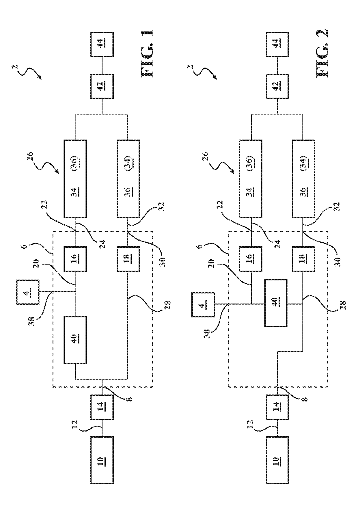
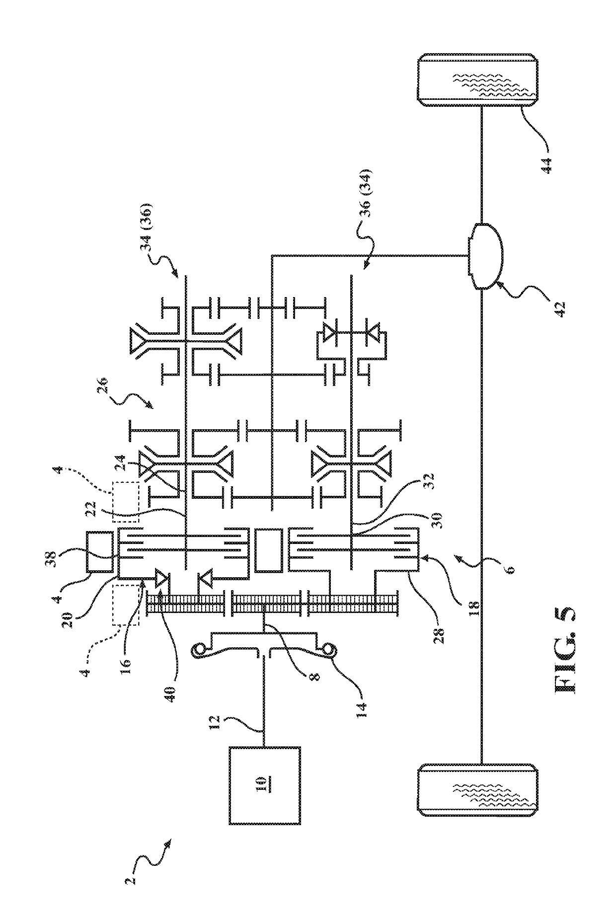
[0028]FIG. 1 shows a drivetrain 2 for a hybrid vehicle. Drivetrain 2 has an electric machine 4 which may be operated both as a generator and as an engine. In addition, drivetrain 2 has a double clutch device 6. Double clutch device 6 has an input side 8 which is assigned to a drive unit 10 in the form of an internal combustion engine. Stated more precisely, an output side 12 of drive unit 10 is in rotational driving connection with input side 8 of double clutch device 6, wherein the rotational driving connection is carried out in this case indirectly via torsional vibration damper 14 which is arranged between input side 8 of double clutch device 6 and output side 12 of drive unit 10.
[0029]Double clutch device 6 has a first clutch arrangement 16 and a second clutch arrangement 18 which are formed preferably as disk clutches, particularly preferred as wet-running disk clutches. First clutch arrangement 16 has a first clutch input side 20 and a first clutch output side 22, wherein firs...
second embodiment
[0034]FIG. 2 shows drivetrain 2 which corresponds substantially to drivetrain 2 of FIG. 1, so that subsequently only the differences will be introduced; identical reference numerals are used for identical or similar parts and the preceding description correspondingly applies in general.
[0035]As is clear from FIG. 2, first clutch input side 20 of first clutch arrangement 16 in the second embodiment is connected to second clutch input side 28 via a freewheel 40 so that first clutch input side 20 of first clutch arrangement 16, via freewheel 40, and second clutch input side 28 of second clutch arrangement 18 are, if necessary, in rotational driving connection with input side 8 of double clutch device 6, whereas second clutch input side 28 is furthermore in continuous rotational driving connection with input side 8 of double clutch device 6 without an intermediary acting freewheel 40, as this has already been previously explained. In general, the preceding embodiments correspondingly ap...
third embodiment
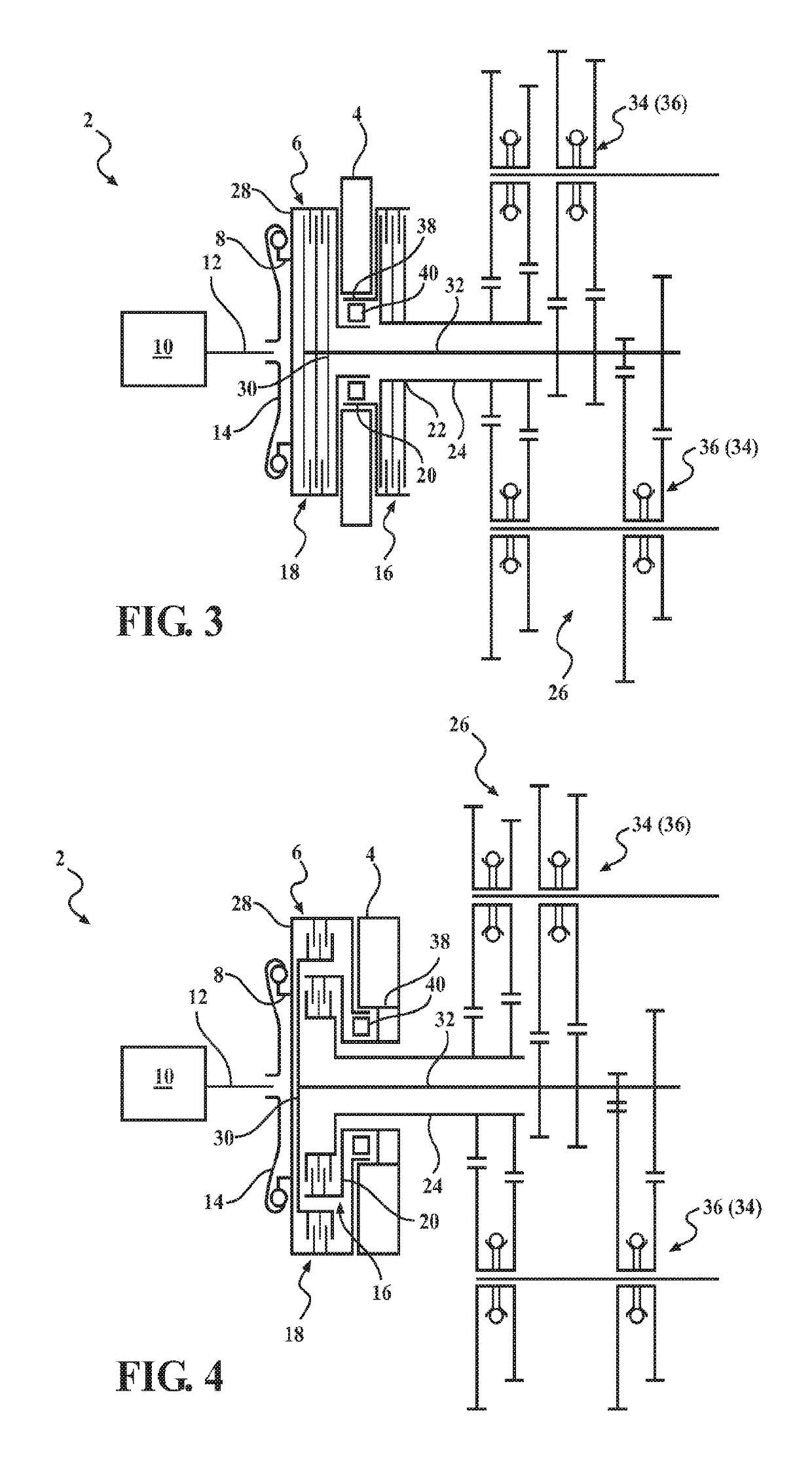
[0036]FIG. 3 shows drivetrain 2 which corresponds substantially to drivetrain 2 of FIG. 2, so that subsequently only the differences will be introduced; identical reference numerals are used for identical or similar parts and the preceding description correspondingly applies in general.
[0037]As is clear in FIG. 3, first and second clutch arrangements 16, 18 are arranged in parallel or axially staggered, wherein the two clutch arrangements 16, 18 of double clutch device 6—as already previously mentioned—are designed as disk clutches. It is also clear in FIG. 3 that electric machine 4 is arranged axially staggered with first and second clutch arrangements 16, 18, wherein electric machine 4 is arranged between first and second clutch arrangements 16, 18 in the axial direction. In general, the preceding embodiments correspondingly apply for the embodiment according to FIG. 3.
PUM
 Abstract
Description
Claims
Application Information
 - R&D
- Intellectual Property
- Life Sciences
- Materials
- Tech Scout
- Unparalleled Data Quality
- Higher Quality Content
- 60% Fewer Hallucinations
Browse by: Latest US Patents, China's latest patents, Technical Efficacy Thesaurus, Application Domain, Technology Topic, Popular Technical Reports.
© 2025 PatSnap. All rights reserved.Legal|Privacy policy|Modern Slavery Act Transparency Statement|Sitemap|About US| Contact US: help@patsnap.com


