Heat spreading module for portable electronic device

a technology of heat spreading module and electronic device, which is applied in the direction of modifications by conduction heat transfer, instruments, and the like, can solve the problems of limited cooling capacity of the cpu, likely dry out of the heat pipe, etc., and achieve excellent heat dissipation performance or the cooling performance of the heating element is not deteriorated, and excellent heat dissipation performan

Active Publication Date: 2019-06-04
FUJIKURA LTD
View PDF18 Cites 2 Cited by
  • Summary
  • Abstract
  • Description
  • Claims
  • Application Information

AI Technical Summary

Benefits of technology

[0008]The present invention has been made in view of the circumstances described above, and provides a heat spreading module capable of achieving both the reduction in the thickness of a portable electronic device and the increase in the cooling capability.
[0011]According to the above-mentioned aspects of the present invention, heat of the heating element is transferred to the heated portion of the heat pipe and the metal plate in the heated region. The heated portion of the heat pipe is formed in the flat shape and arranged inside the hole portion formed in the metal plate. The metal plate is not interposed between the heating element and the heated portion of the heat pipe. Therefore, the heat spreading module or a portable electronic device using the heat dissipation plate can be thinned. According to the above-mentioned aspects of the present invention, heat of the heating element is transferred not only to the heated portion of the heat pipe but also to the metal plate. Therefore, the amount of heat input to the heated portion of the heat pipe is moderated, whereby dry-out hardly occurs even though the heated portion is formed in the flat shape, and the heat dissipation performance or the cooling performance for the heating element is not deteriorated.
[0012]According to the above-mentioned aspects of the present invention, the heat dissipation portion of the heat pipe is thicker than the heated portion, whereby vapor of a working fluid flows smoothly. Furthermore, the heat dissipation portion is brought into close contact with the metal plate. Therefore, the heat pipe has the excellent heat transfer performance, and moreover, the excellent heat dissipation performance.

Problems solved by technology

When the amount of heat generation in the CPU is large, therefore, dry-out of the heat pipe is likely to occur, whereby capability to cool down the CPU might be limited.

Method used


Image

  • Heat spreading module for portable electronic device
  • Heat spreading module for portable electronic device
  • Heat spreading module for portable electronic device

Examples


example 1

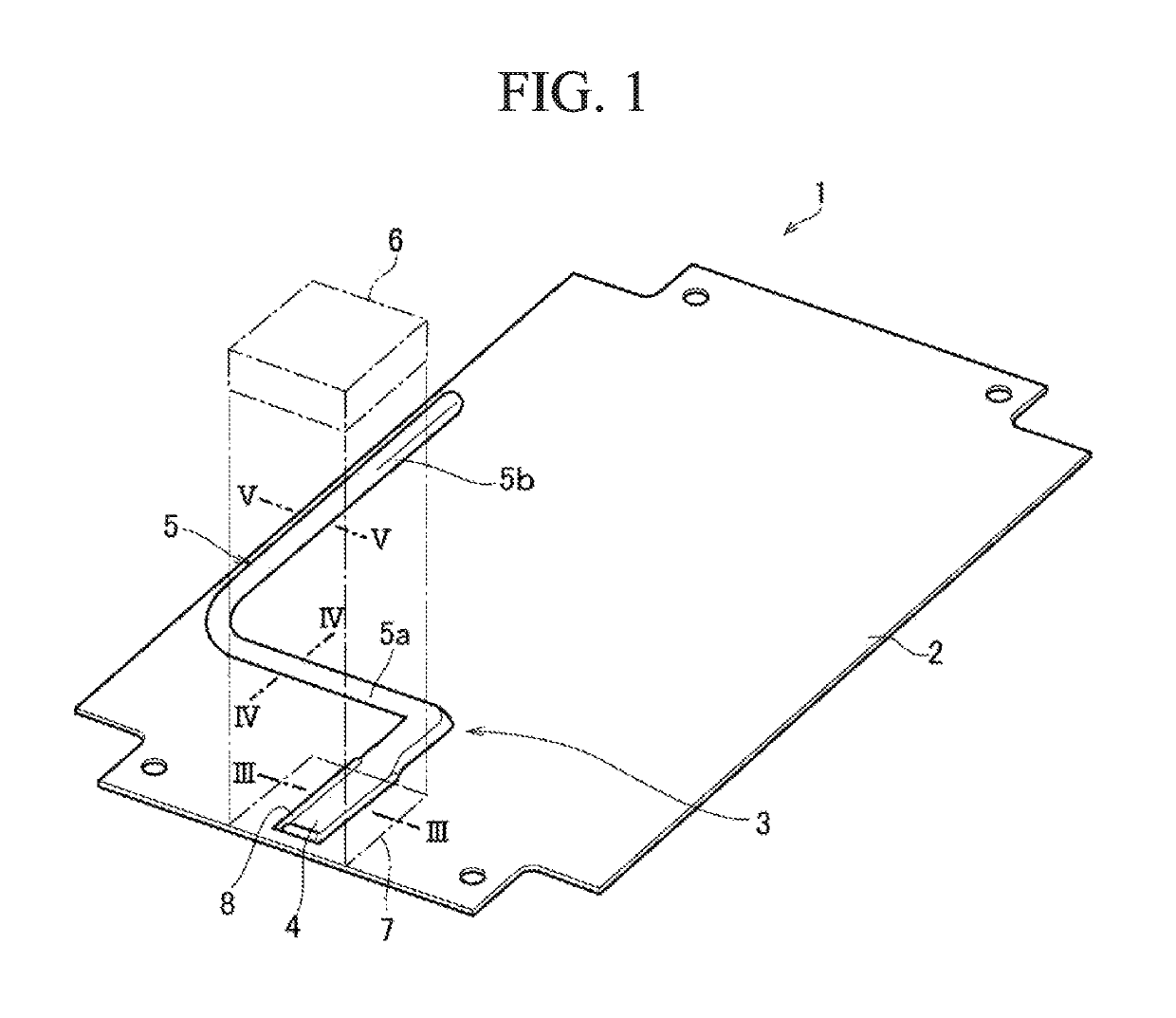
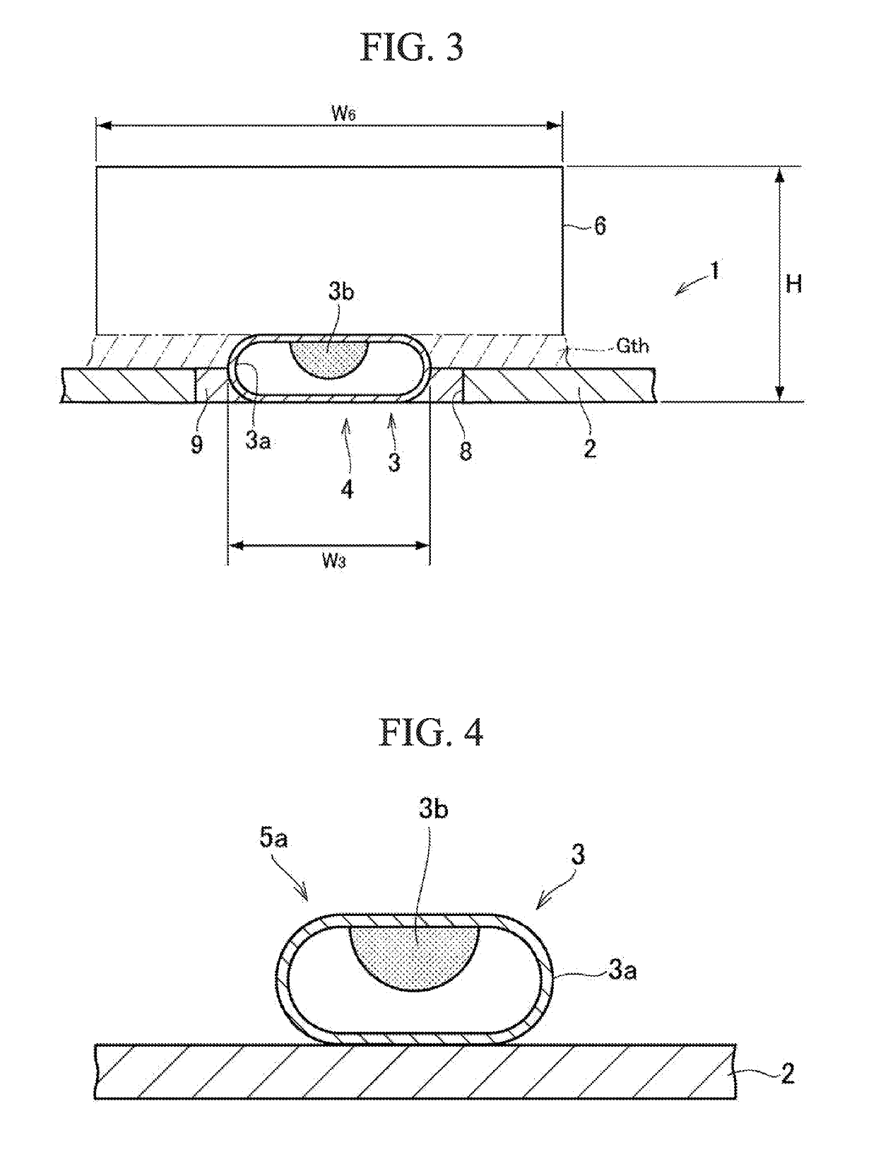
[0034]A copper plate having a thickness of 0.2 mm was used as the metal plate. A heat pipe configured in such a manner that the wick made of a thin copper wire was arranged inside a copper pipe and water was contained as the working fluid was used as the heat pipe. The heated portion was processed flatly so as to have a thickness of 0.4 mm. The heat dissipation portion was processed into a flat shape having a thickness of 0.6 mm. The heated portion of the heat pipe was arranged inside the hole portion formed in the metal plate. The heated region, therefore, has a maximum thickness of 0.4 mm in the heated portion. As a substitute for the heating element, a heater, the output of which is adjustable, was brought into contact with the heated region. The temperature of the heated portion was measured when the output of the heater was set to 3 W, 4 W, and 5 W. The result of the measurement of the temperature is illustrated in Table 1.

example 2

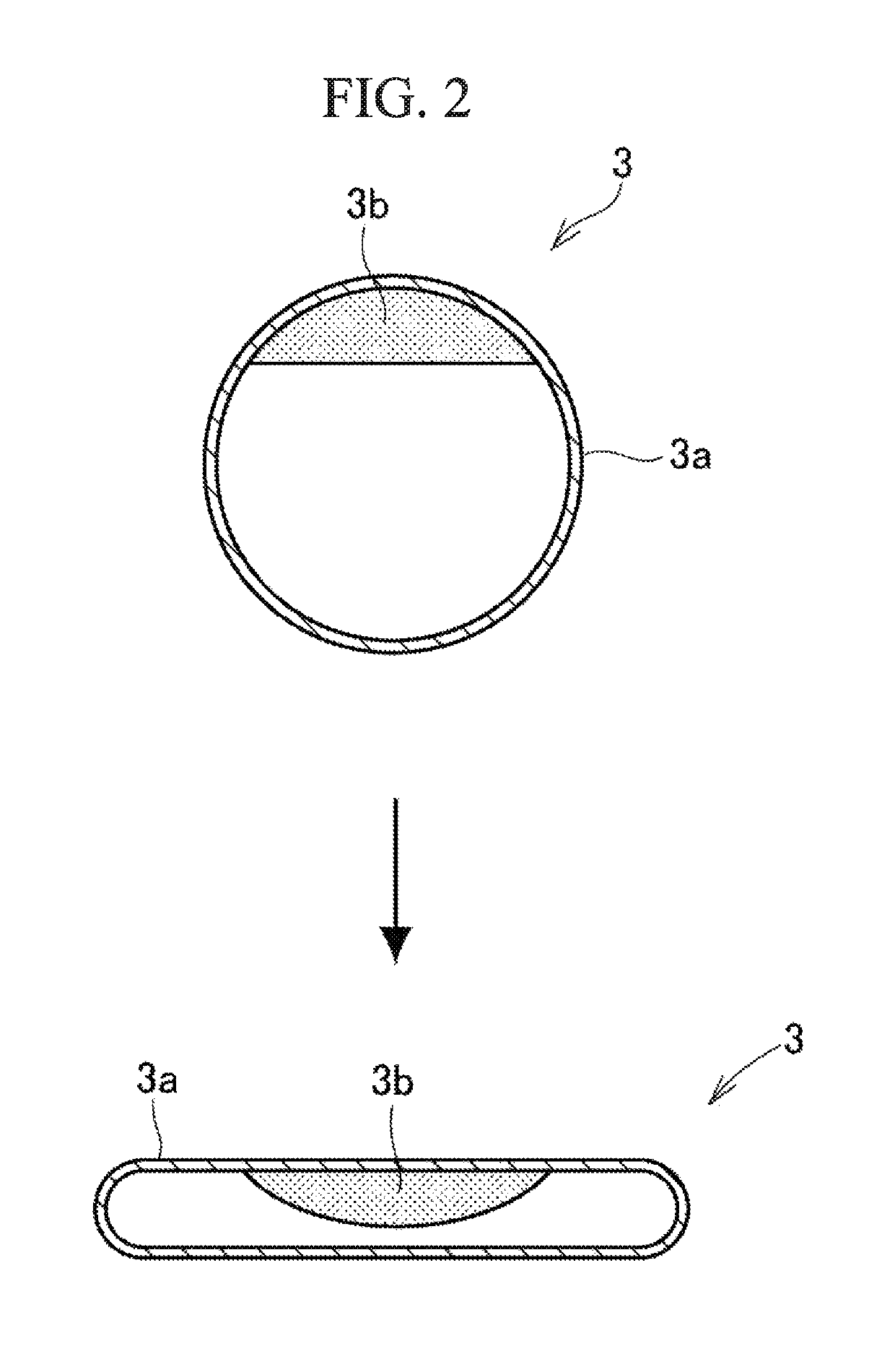
[0035]The metal plate and the heat pipe similar to those of Example 1 described above were used. The aforementioned heat transfer material illustrated in FIG. 6 was provided on the heated region, and the thickness of the heat transfer material was 0.05 mm. Accordingly, the thickness of the heated portion was set to 0.35 mm, whereby the heated region had a maximum thickness of 0.4 mm as was the case in Example 1. In the same way as Example 1 described above, as a substitute for the heating element, a heater, the output of which is adjustable, was brought into contact with the heated region. The temperature of the heated portion was measured when the output of the heater was set to 3 W, 4 W, and 5 W. The result of the measurement of the temperature is illustrated in Table 1.


PUM


Abstract

In a heat spreading module for a portable electronic device configured such that a heat pipe is attached along a metal plate with which a heating element is brought into close contact, and heat of a heated region of the metal plate with which the heating element is brought into close contact is transferred to a place on the metal plate apart from the heated region by the heat pipe, the heat pipe is configured such that a container is formed of a pipe, a portion of the container arranged on the heated region is a heated portion, and a portion of the container apart from the heated region is a heat dissipation portion that dissipates heat to the metal plate, and the heated portion is formed in a flat shape, and the heat dissipation portion is formed to be thicker than the heated portion having the flat shape.

Description

CROSS REFERENCE TO RELATED APPLICATIONS[0001]Priority is claimed on Japanese Patent Application No. 2015-162134, filed Aug. 19, 2015, the content of which is incorporated herein by reference.BACKGROUND OF THE INVENTION[0002]Field of the Invention[0003]The present invention relates to a heat spreading module that is used for a portable electronic device such as a multifunctional mobile phone (smartphone) and a tablet personal computer.[0004]Description of Related Art[0005]A portable information terminal configured to transfer heat of a heating element to a low temperature portion by a heat pipe is described in Japanese Unexamined Patent Application, First Publication No. 2014-165596 A. The heat pipe is configured such that a copper tube is sealed at both ends thereof and a working fluid is contained inside the copper tube. A central portion of the heat pipe is arranged on an upper surface of the heating element, that is, a CPU, and both end sides extend to a battery side along a side...

Claims


Application Information

Patent Timeline
Patent Type & Authority Patents(United States)
IPC IPC(8): H05K7/20G06F1/20H04M1/02F28D15/02F28D15/04H01L23/427F28F13/00
CPCH05K7/20336F28D15/0233F28D15/0275F28D15/04H01L23/427H04M1/0202H05K7/20509G06F1/203F28F2013/006H05K7/2039
Inventor AHAMED, MOHAMMAD SHAHEDSAITO, YUJITAKAMIYA, AKIHIROTAKAHASHI, MAKOTO
Owner FUJIKURA LTD
Why Eureka
Try Eureka