
Digital signal processing array using integrated processing elements

a technology of integrated processing elements and digital signal processing, which is applied in the direction of multi-programming arrangement, pulse technique, instruments, etc., can solve the problems of slow and laborious cycle between design and testing, inability to use a large percentage of the available resources of fpga dsp, and difficulty in designing complex logic with basic hardware description languages, etc., to minimize or eliminate redundant processing, and reduce the number of redundant processing

Active Publication Date: 2019-07-16
ACORN INNOVATIONS INC
View PDF3 Cites 1 Cited by
  • Summary
  • Abstract
  • Description
  • Claims
  • Application Information

AI Technical Summary

Benefits of technology

The patent describes a system with processing elements arranged in a grid having two dimensions. The processing elements are configured to receive input data along the second dimension to minimize or eliminate redundant processing. The data input and output to the local register file is implemented as a ring buffer. The processing elements can be arranged to eliminate redundancy in processing data along the first and second dimensions. The technical effect of this system is reduced processing redundancy, improved processing efficiency, and improved data processing speed.

Problems solved by technology

The main drawback to using FPGAs has been the difficulty involved in designing complex logic with basic hardware description languages (HDL) and the slow and laborious cycle between design and testing.
However, due to their costly connection and data alignment logic requirements, a typical array implemented in FPGA is unable to use a large percentage of the FPGA DSP resources available and typically does not exceed a modest number of PEs, such as 16.
To date, all of these implementations have remained inadequate for many challenging applications such as real-time, large-format video processing due to limitations in processing and I / O performance resulting from the array architecture and the addition of programmability.
Hence, none of these implementations have achieved widespread commercial success.

Method used


Image

  • Digital signal processing array using integrated processing elements
  • Digital signal processing array using integrated processing elements
  • Digital signal processing array using integrated processing elements

Examples


example embodiments

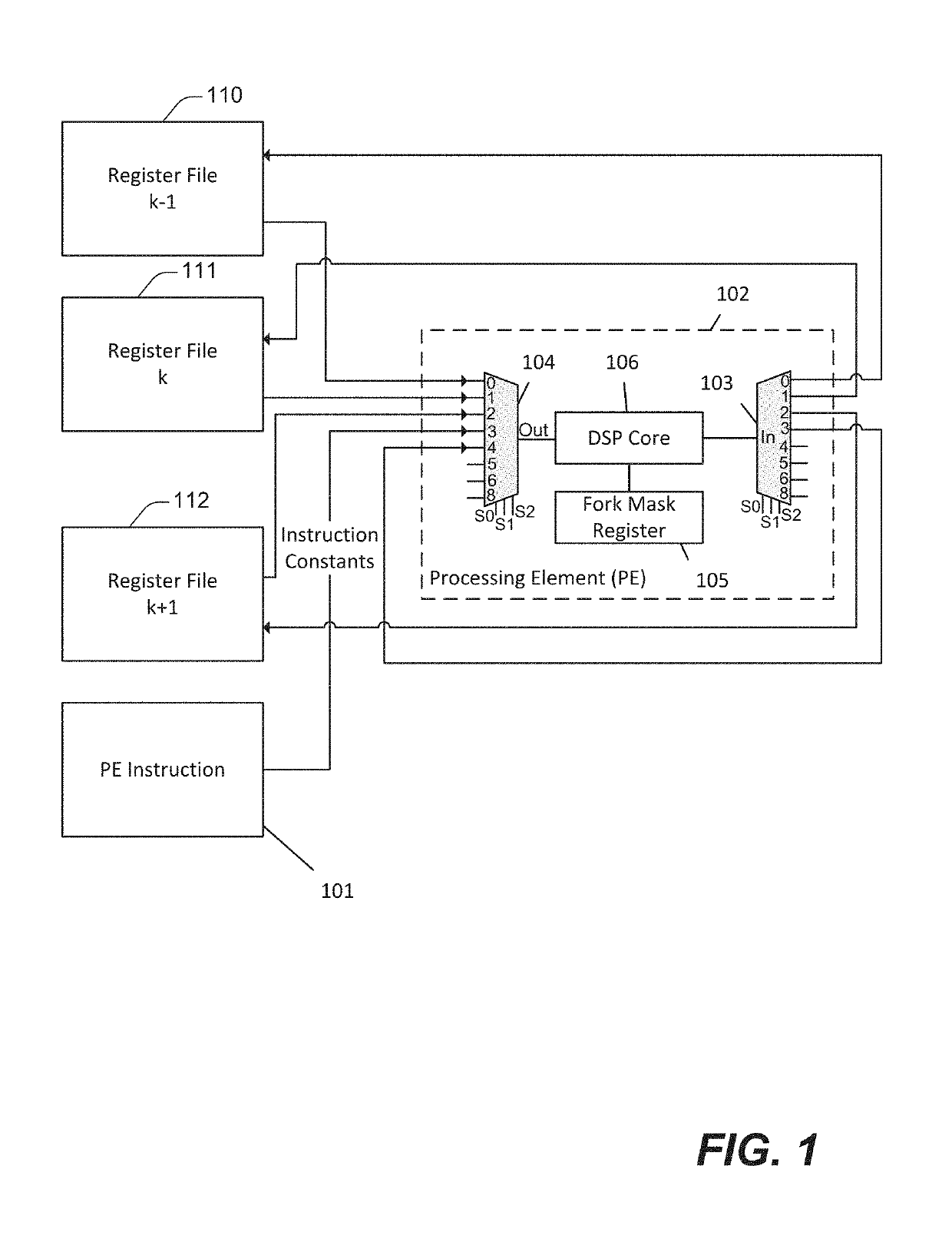
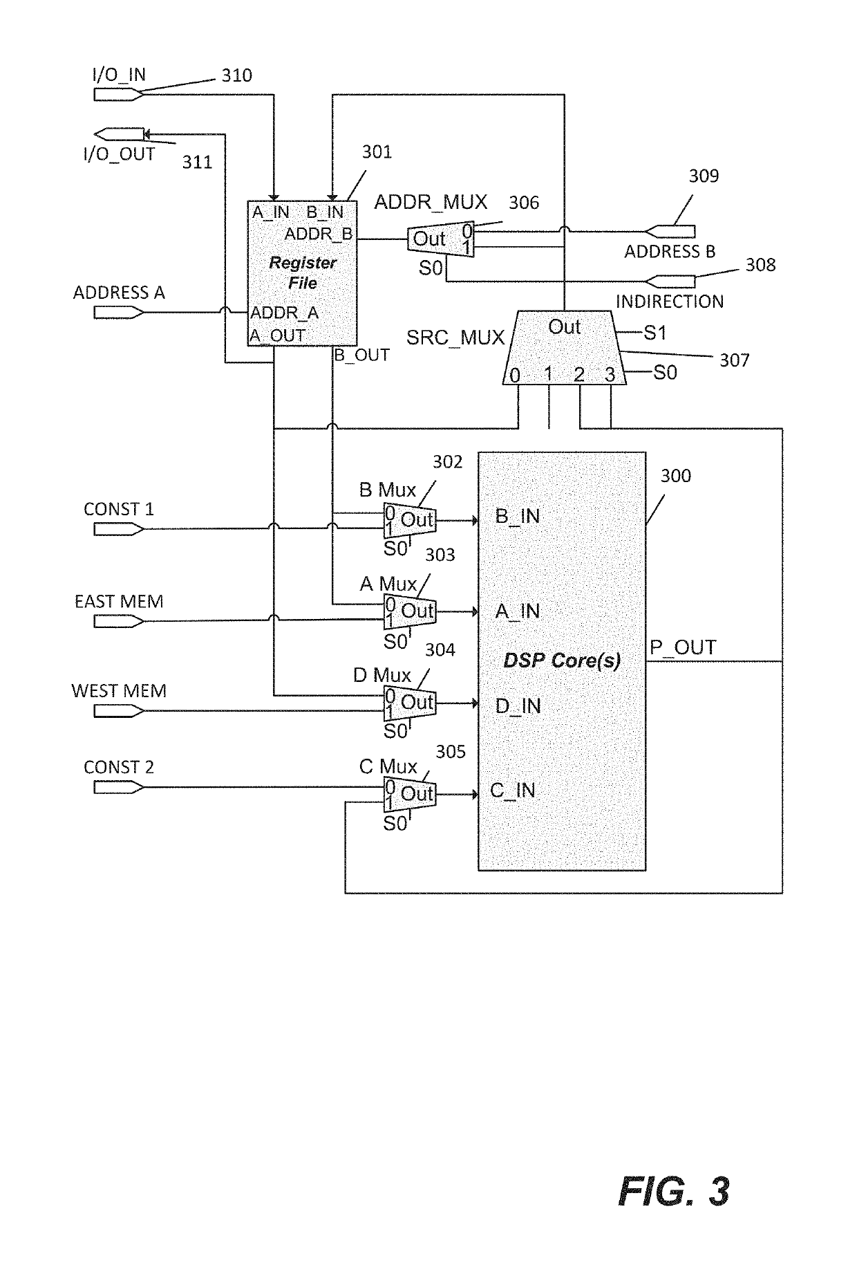
[0036]According to various embodiments, techniques and mechanisms described herein include a new, high level language programmable processing architecture with significant input / output and computational advantages without the limitations of conventional FPGA overlays. In some embodiments, this architecture includes arrays of hardened DSP cores and register files interspersed with generic logic elements (LEs) and interconnected in a single or bi-dimensional lattice. The processor also includes auxiliary logic modules, which include components such as an instruction sequencer, an external I / O controller module, mask registers for conditional execution, and LEs for data pathway selection.

[0037]In some embodiments, techniques and mechanisms described herein also include a highly efficient, FPGA-based signal processing overlay that addresses limitations of conventional vector overlay approaches. This new architecture may be referred to herein as a tile overlay, while a processor that ref...


PUM


Abstract

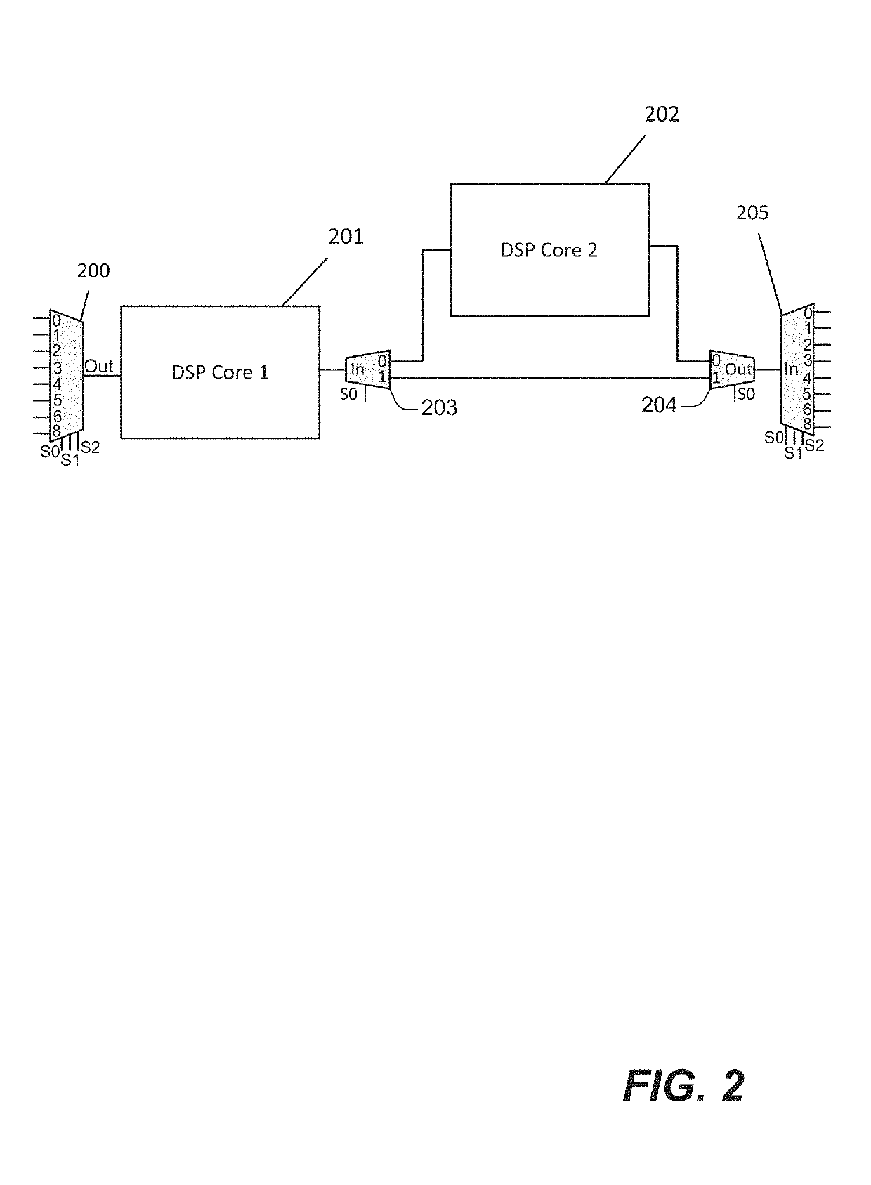
Techniques and mechanisms described herein include a signal processor implemented as an overlay on a field-programmable gate array (FPGA) device that utilizes special purpose, hardened intellectual property (IP) modules such as memory blocks and digital signal processing (DSP) cores. A Processing Element (PE) is built from one or more DSP cores connected to additional logic. Interconnected as an array, the PEs may operate in a computational model such as Single Instruction-Multiple Thread (SIMT). A software hierarchy is described that transforms the SIMT array into an effective signal processor.

Description

TECHNICAL FIELD[0001]The present disclosure relates generally to the configuration of computer processors, and more specifically to the configuration of field programmable gate arrays and application specific integrated circuits for the parallel processing of digital signals.DESCRIPTION OF RELATED ART[0002]In recent years, field programmable gate arrays (FPGAs) have emerged as a power-efficient alternative to graphics processing units (GPUs) and multiple-core central processing units (CPUs) for the implementation of complex algorithms in real-time or near real-time applications. In its 2015 investor meeting, Intel estimated that FPGAs will be used in 30% of data center servers by 2020. The main drawback to using FPGAs has been the difficulty involved in designing complex logic with basic hardware description languages (HDL) and the slow and laborious cycle between design and testing. The introduction of high-level synthesis (HLS) has somewhat mitigated these challenges, but the issu...

Claims


Application Information

Patent Timeline
Patent Type & Authority Patents(United States)
IPC IPC(8): G06F15/167G06F9/30G06F15/80G06F9/54
CPCG06F9/3005G06F15/80G06F9/3004G06F15/7867H03K19/17764G06F9/323
Inventor DEAME, JOHN E.KAUFMANN, STEVENVOICU, LIVIU
Owner ACORN INNOVATIONS INC
Learn More