
Sustained release system for reservoir treatment and monitoring

a technology for reservoir treatment and monitoring, which is applied in the direction of survey, wellbore/well accessories, construction, etc., can solve the problems of reducing well productivity, shortening the life of production equipment, and preventing production from affecting the effect of production

Active Publication Date: 2019-08-06
TRACERCO LTD
View PDF10 Cites 2 Cited by
  • Summary
  • Abstract
  • Description
  • Claims
  • Application Information

AI Technical Summary

Benefits of technology

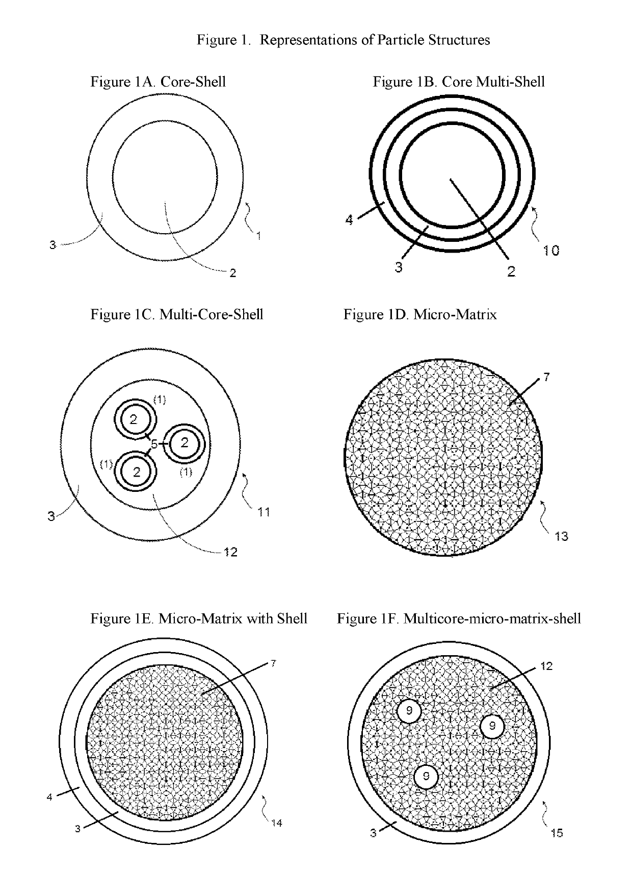
This patent describes a way to deliver and release oil field chemicals in a controlled and sustained manner over a long period of time. The invention can be used in solid, liquid, or gaseous form, and it minimizes the effects of using chemicals with different properties. The invention also allows for the easy formulation and delivery of oil field chemicals, as well as the monitoring and tracing of fluid flow in a hydrocarbon reservoir. The invention includes a composition of microcapsules containing oil field chemicals and a polymeric microencapsulant, which are embedded within a bulk polymer. The microcapsules can have various structures and can provide for the slow release of the oil field chemical over time. The methods for using the invention include placing the composition in a well or reservoir and allowing the oil field chemical to diffuse into the surrounding fluids. The invention also allows for the tracing of fluid flow from the reservoir by placing the composition and collecting samples of the flow.

Problems solved by technology

This, in turn, decreases permeability of the subterranean formation, reduces well productivity and shortens the lifetime of production equipment.
In order to remove such unwanted deposits and precipitates from wells and equipment, it is necessary to stop the production which is both time-consuming and costly.
Despite the very wide usage of oil field chemicals, many of the current methods of introducing and using these chemicals have disadvantages.
One issue is the difficulty in handling oilfield chemicals that are in different physical states.
Compared to solid tracers, tracers in liquid and gas form are often difficult to formulate and shape into stable solid objects.
This can limit the types of tracers that can be used.
Another issue is that some oil field chemicals are reactive, making them difficult to formulate and deliver into the reservoir.
A further issue is that unwanted inhomogeneous compositions can result from formulating some oil field chemicals.
For example, it is known that the density of oil tracers can vary from 1 to 3 g / cm3 and these differences can result in various problems.
The differences between the densities of the tracers can result in compositions comprising a tracer and polymer having significant non-homogeneous structure and morphology.
Such non-homogeneous objects tend to show undesired release behavior in a subterranean reservoir environment.
Although the use of an extra dispersing / stabilizing additive in the formulation of the objects can partially alleviate this problem, other associated problems, such as poor mechanical strength in a reservoir environment, remain.
As a result, sometimes even apparently similar tracers in one family cannot be formulated in the same way.
One of the most important issues is the release of oil field chemicals from formulated articles to the targeted fluid or reservoir areas.
While it is often a requirement for oil field chemicals to be released in a sustained manner, e.g. slowly so that treatment can be effective over long periods of time (e.g., years), the release of the chemicals in current commercial practice is often too fast (less than 6 months) and not up to the needs of the industry.
The release of oil field chemicals, such as tracers, is often not controlled in current practice, causing significant variations over time for both a single tracer and as well as between different tracers.
Such issues often result in ineffective treatments or loss of monitoring of the reservoir, and result in lost production revenue due to down time and the costs of the additional materials that are used retreat the wells.

Method used


Image

  • Sustained release system for reservoir treatment and monitoring
  • Sustained release system for reservoir treatment and monitoring
  • Sustained release system for reservoir treatment and monitoring

Examples


example 1

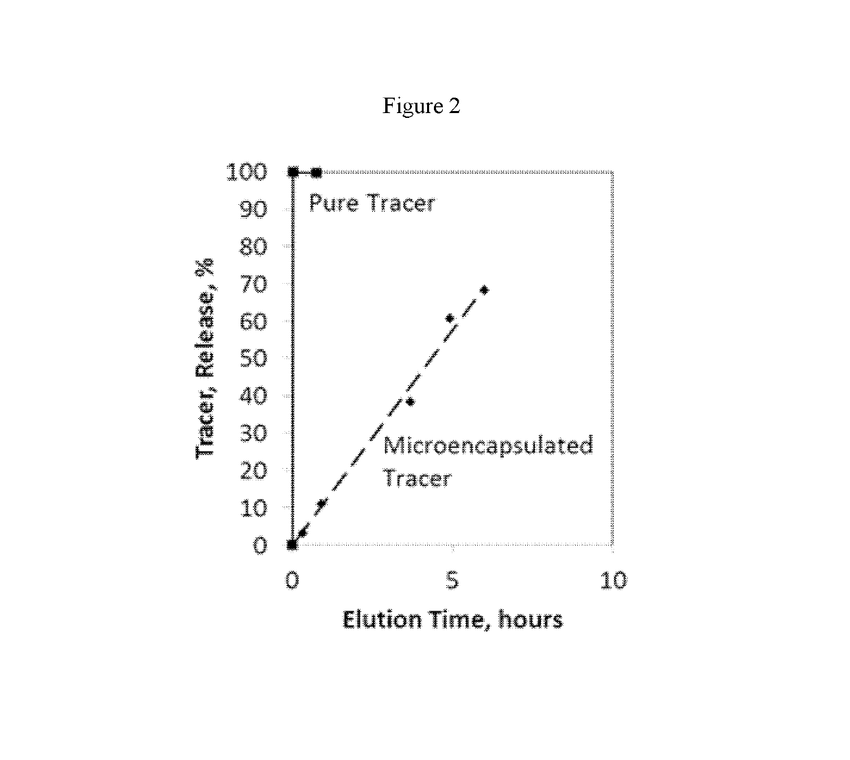
ion of Microcapsules Containing a Tracer and Elution of Pure Tracer and the Tracer from Microcapsules

[0225]A tracer (Tracer A: a solid haloaromatic compound, density 2.3 g / cm3 at 25° C. and 1 atm) was ground and filtered through a 100 μm sieve. 1.2 g carboxylmethylcellulose sodium salt (Sigma) was dissolved in 78.3 g water and then mixed with 15.9 g Beetle resin (BIP) and 0.35 g formic acid (96%, Sigma) to form an aqueous mixture. The aqueous mixture was stirred at 25° C. for 1 hour. 60 g of the sieved tracer and the aqueous mixture were then homogenised together for 5 minutes using a Silverson L4R laboratory homogeniser. During the homogenisation process, 300 g water was added to dilute the mixture. The homogenised mixture was stirred at 25° C. for 2 hours and then at 65° C. for 2 more hours. The resultant dispersion was filtered, dried in air for 3 days and then dried in a vacuum oven at 50° C. for 8 hours. The dried powder product containing the encapsulated tracer was filtered t...

example 2

on of Sustained Release Articles with Microencapsulated Oil Tracer

[0227]A mixture of 10 g microencapsulated oil tracer particles obtained from Example 1, 9 g bisphenol A diglycidyl ether (Sigma) and 1 g triethylenetetramine (technical grade, Sigma) were combined in a plastic container and mixed with a stainless steel spatula. The mixture was transferred to a 25 mL plastic syringe and injected into silicon moulds. The moulds were in a cylindrical shape with a radius of 0.9 cm and a height of 1.1 cm. The moulded composition was cured in an oven at 60° C. for 2 hours. The articles in the shape of a cylinder were easily removed from the moulds. The articles contained 41% by weight of tracer A. The cylinder appeared to be uniform throughout and showed only a very faint colour.

example 3

est of an Oil Tracer from Sustained Release Articles into Toluene

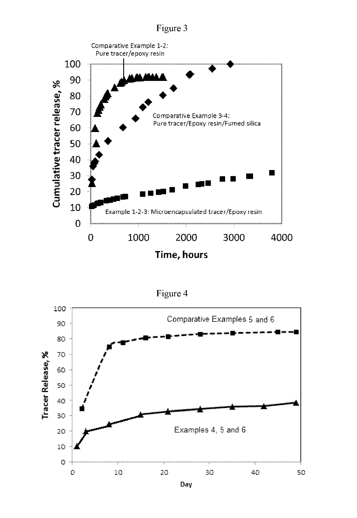
[0228]Toluene was used as a model oil for characterising the elution of tracer from articles in the shape of cylinders. A cylinder made from Example 2 (mass: 3.4705 g) was suspended in a glass bottle containing 150 mL of toluene. Toluene and the cylinder were stirred at a temperature of 60° C. and samples (˜0.5 mL) of toluene were taken from the bottle at various times. The samples were diluted, if necessary, and analysed using GC-MS or GC-ECD. In order to maintain the total amount of toluene in the test bottle, ˜0.5 mL of fresh toluene was injected into the test bottle each time after a sample was taken.

[0229]The entire amount of toluene inside the test bottle was also replaced with fresh toluene at various times. The cumulative concentration of tracer released was calculated by adding the concentration of the tracer in the toluene in the bottle that is mixed with the article to the final concentrations of tracer in t...


PUM

PropertyMeasurementUnit
volume weighted average particle sizeaaaaaaaaaa
densityaaaaaaaaaa

Abstract

Compositions containing a mixture of microcapsules and a bulk polymer, where the microcapsules have an oil field chemical contained within the microcapsules are provided. The microcapsules can be present in a variety of configurations. The microcapsules contain a core or a micro-matrix containing the oil field chemicals. The core or micro-matrix can be surrounded by one or more polymeric shells, where each shell contains at least one polymer that affects the release of the oil field chemical from the composition. The compositions provide for the sustained release of an oil field chemical into fluid in an oil field reservoir over long periods of time. Methods of making the compositions and articles containing the compositions are also provided. Further provided are methods of tracing the movement of fluid in a hydrocarbon reservoir using the compositions, and methods of providing for the sustained release of oil field chemicals.

Description

CROSS-REFERENCE TO RELATED APPLICATIONS[0001]This application is the National Stage of International Patent Application No. PCT / GB2016 / 051172 filed Apr. 26, 2016, which claims priority from Great Britain Patent Application No. 1507479.2 filed Apr. 30, 2015, the disclosures of each of which are incorporated herein by reference in their entireties for any and all purposes.FIELD OF THE INVENTION[0002]The present invention is directed towards compositions comprising a mixture of a bulk polymer with microcapsules containing one or more oil field chemicals within the microcapsules. Articles comprising microcapsules incorporated into a continuous bulk polymer matrix can provide for the sustained release of the oil field chemical into oil field fluids over periods of time from weeks to years.BACKGROUND OF THE INVENTION[0003]It is common practice to deliver oilfield chemicals to a subterranean hydrocarbon reservoir to bring about a variety of functions at various stages of hydrocarbon produc...

Claims


Application Information

Patent Timeline
Patent Type & Authority Patents(United States)
IPC IPC(8): E21B47/10E21B43/267E21B49/08C09K8/52C09K8/035C09K8/58C09K8/92E21B41/02E21B37/06
CPCC09K8/92C09K8/035C09K8/52C09K8/58E21B47/1015E21B49/08E21B43/267E21B41/02E21B37/06C09K8/72E21B43/00E21B47/00E21B47/111
Inventor BORRELL, NEILZHAO, CHUN-TIAN
Owner TRACERCO LTD
Learn More