

Sustained release system for reservoir treatment and monitoring
a technology for reservoir treatment and monitoring, which is applied in the direction of survey, wellbore/well accessories, construction, etc., can solve the problems of reducing well productivity, shortening the life of production equipment, and preventing production from affecting the effect of production
- Summary
- Abstract
- Description
- Claims
- Application Information
AI Technical Summary
Benefits of technology
Problems solved by technology
Method used
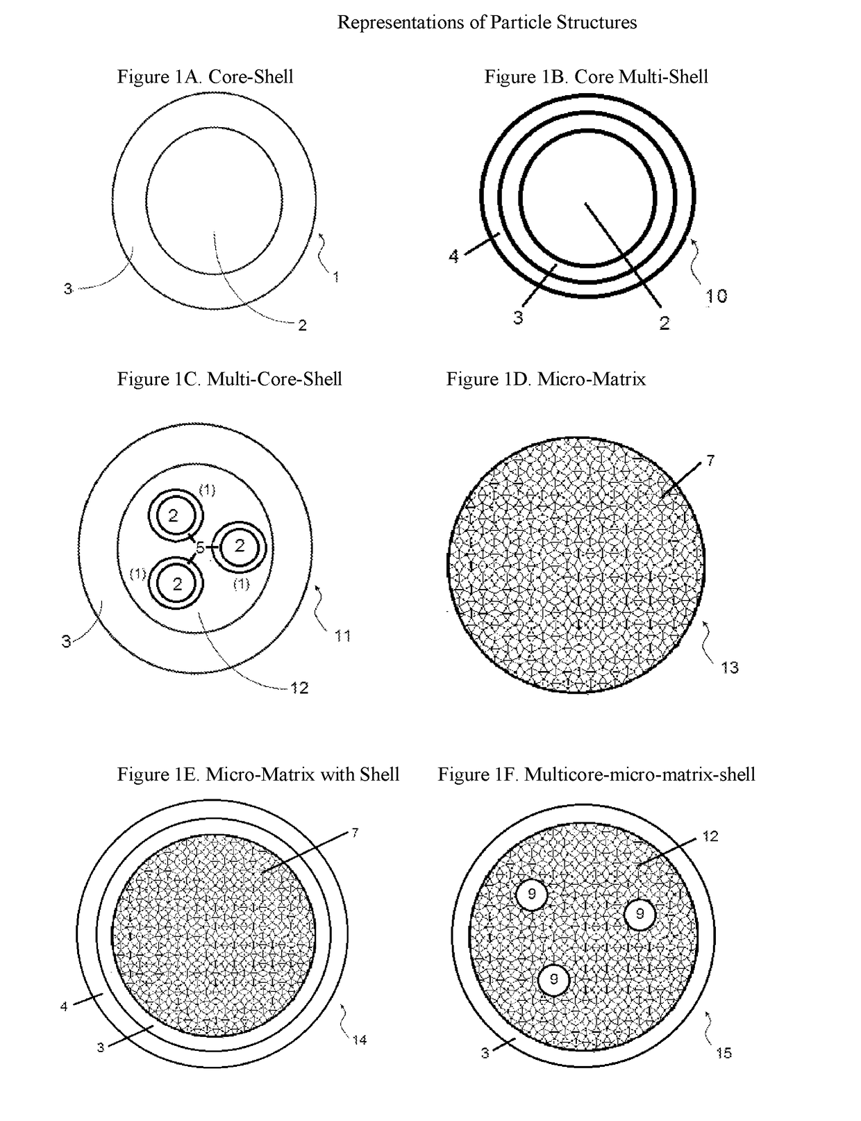
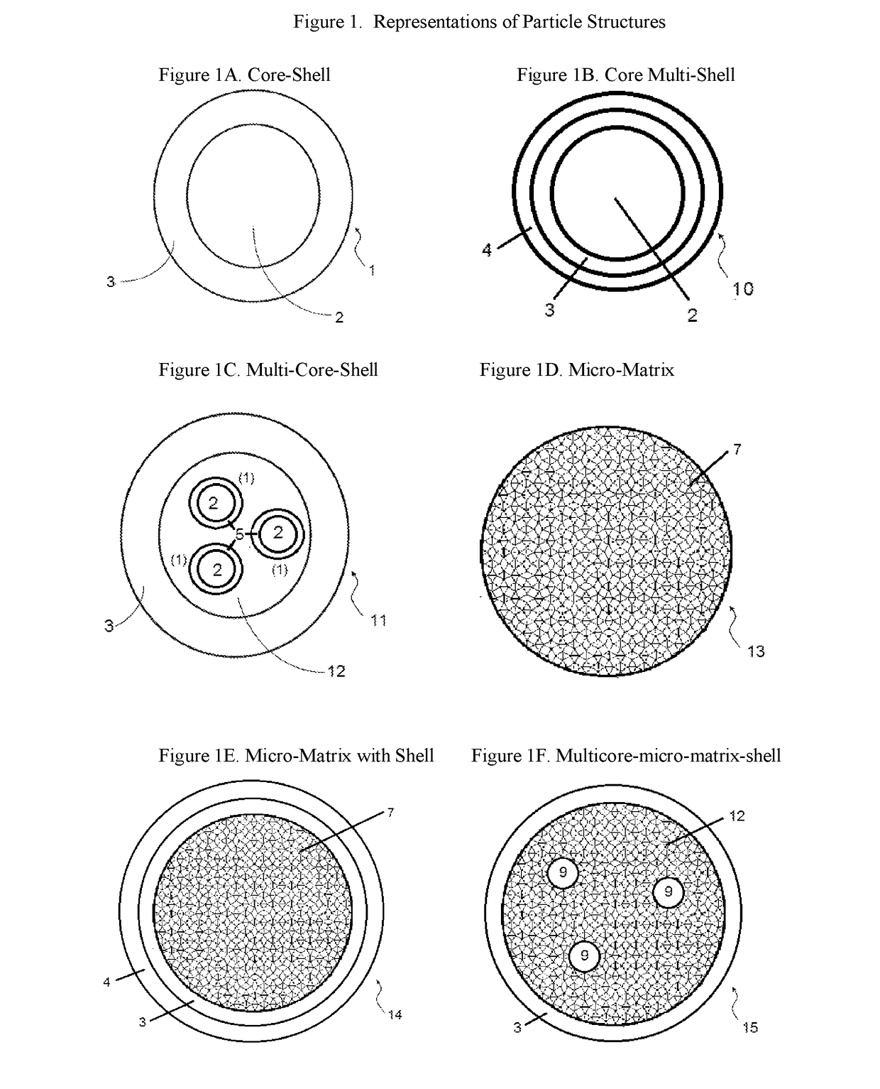
Image

Examples
example 1
ion of Microcapsules Containing a Tracer and Elution of Pure Tracer and the Tracer from Microcapsules
[0222]A tracer (Tracer A: a solid haloaromatic compound, density 2.3 g / cm3 at 25° C. and 1 atm) was ground and filtered through a 100 μm sieve. 1.2 g carboxylmethylcellulose sodium salt (Sigma) was dissolved in 78.3 g water and then mixed with 15.9 g Beetle resin (BIP) and 0.35 g formic acid (96%, Sigma) to form an aqueous mixture. The aqueous mixture was stirred at 25° C. for 1 hour. 60 g of the sieved tracer and the aqueous mixture were then homogenised together for 5 minutes using a Silverson L4R laboratory homogeniser. During the homogenisation process, 300 g water was added to dilute the mixture. The homogenised mixture was stirred at 25° C. for 2 hours and then at 65° C. for 2 more hours. The resultant dispersion was filtered, dried in air for 3 days and then dried in a vacuum oven at 50° C. for 8 hours. The dried powder product containing the encapsulated tracer was filtered t...
example 2
on of Sustained Release Articles with Microencapsulated Oil Tracer
[0224]A mixture of 10 g microencapsulated oil tracer particles obtained from Example 1, 9 g bisphenol A diglycidyl ether (Sigma) and 1 g triethylenetetramine (technical grade, Sigma) were combined in a plastic container and mixed with a stainless steel spatula. The mixture was transferred to a 25 mL plastic syringe and injected into silicon moulds. The moulds were in a cylindrical shape with a radius of 0.9 cm and a height of 1.1 cm. The moulded composition was cured in an oven at 60° C. for 2 hours. The articles in the shape of a cylinder were easily removed from the moulds. The articles contained 41% by weight of tracer A. The cylinder appeared to be uniform throughout and showed only a very faint colour.
example 3
est of an Oil Tracer from Sustained Release Articles into Toluene
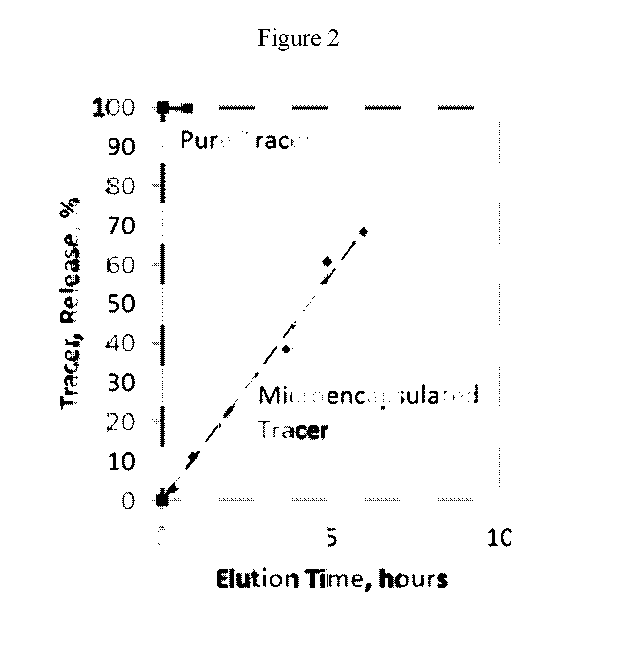
[0225]Toluene was used as a model oil for characterising the elution of tracer from articles in the shape of cylinders. A cylinder made from Example 2 (mass: 3.4705 g) was suspended in a glass bottle containing 150 mL of toluene. Toluene and the cylinder were stirred at a temperature of 60° C. and samples (˜0.5 mL) of toluene were taken from the bottle at various times. The samples were diluted, if necessary, and analysed using GC-MS or GC-ECD. In order to maintain the total amount of toluene in the test bottle, ˜0.5 mL of fresh toluene was injected into the test bottle each time after a sample was taken.
[0226]The entire amount of toluene inside the test bottle was also replaced with fresh toluene at various times. The cumulative concentration of tracer released was calculated by adding the concentration of the tracer in the toluene in the bottle that is mixed with the article to the final concentrations of tracer in t...
PUM
 Abstract
Description
Claims
Application Information