
In-situ forming foams for treatment of aneurysms

a technology of aneurysms and foams, applied in the field of in-situ forming foams for the treatment of aneurysms, can solve the problems of difficult implementation, difficult treatment of internal wounds and bleeding sites, and inability to immediately access surgical care, so as to prevent dislocation of foam and effectively wet tissues

Active Publication Date: 2019-09-24
MEDTRONIC VASCULAR INC
View PDF106 Cites 3 Cited by
  • Summary
  • Abstract
  • Description
  • Claims
  • Application Information

AI Technical Summary

Benefits of technology

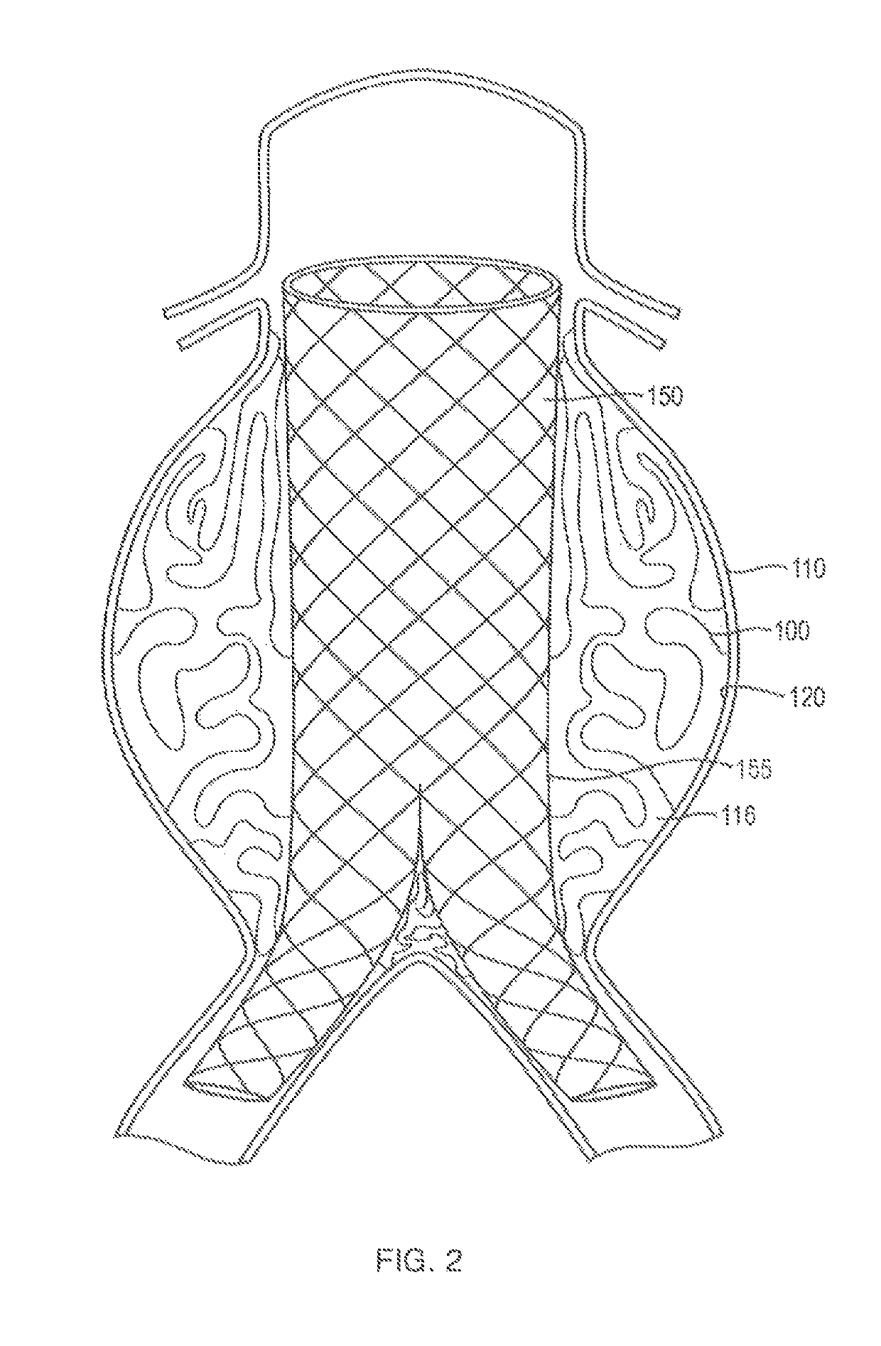
The in-situ forming foams effectively reduce intra-aneurysmal pressure, prevent endoleaks, and provide conformal contact with the aneurysm walls, anchoring the stent-graft and stabilizing it, thus improving the efficacy of EVAR procedures by minimizing the risk of aneurysm expansion or rupture.

Problems solved by technology

In many situations, however, immediate access to surgical care is not available.
Internal wounds and bleeding sites may be particularly difficult to treat in such situations, as traditional treatment techniques (e.g., application of pressure to stop bleeding, etc.) are difficult to implement with such wounds.
Although the use of polymers in the treatment of wounds is well known in the art, previous materials and methods for treating wounds with polymers have suffered from a variety of drawbacks.
Moreover, many polymers lack suitable mechanical properties to be useful inside the body; polymers that are too stiff may lead to discomfort or further injury, while polymers that are too soft may fail to provide adequate support for internal tissues.
In addition, polymers can be difficult to place within internal wounds or bleeding sites that may have complex shapes and geometries.
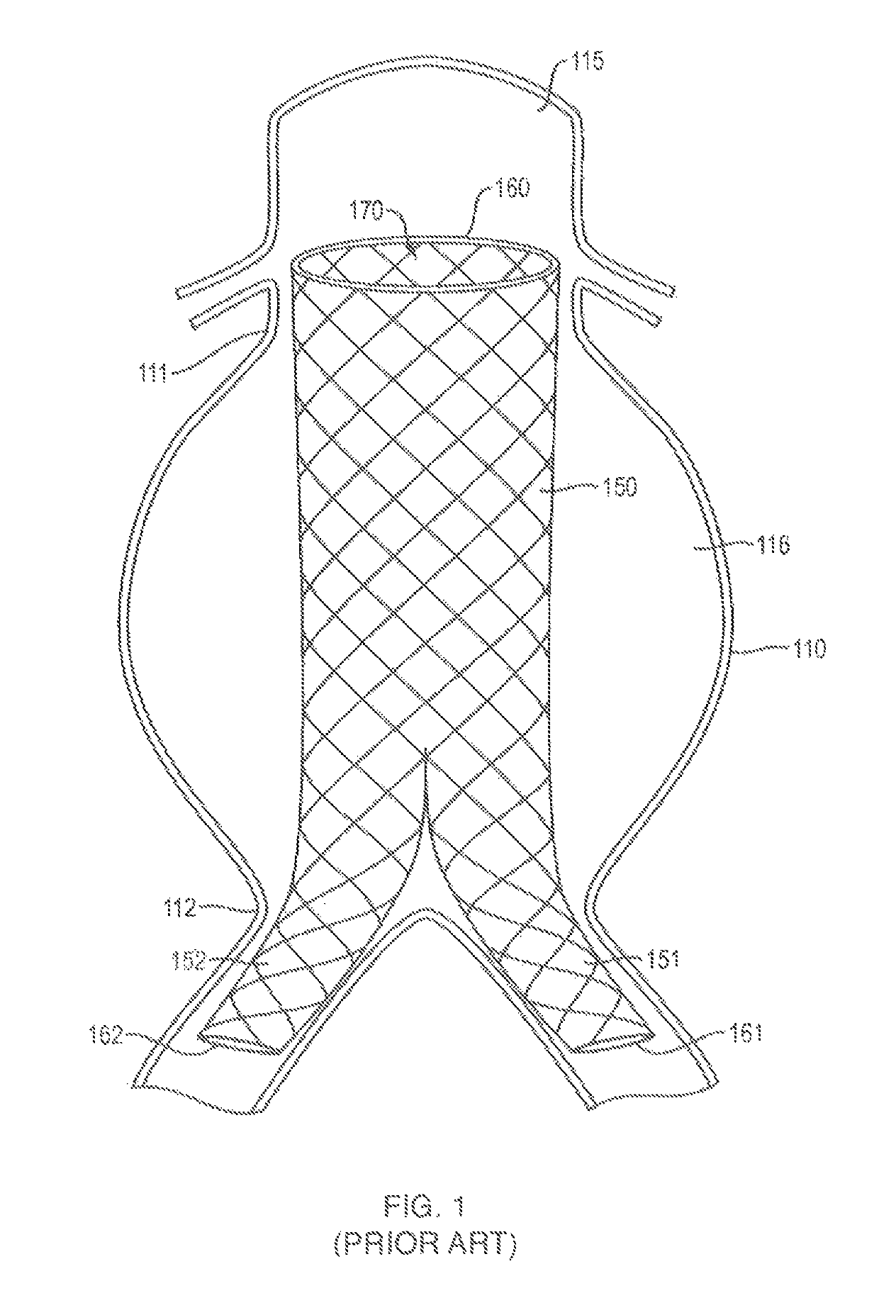
If left untreated, aneurysms can grow large and rupture, causing internal bleeding which is often fatal.
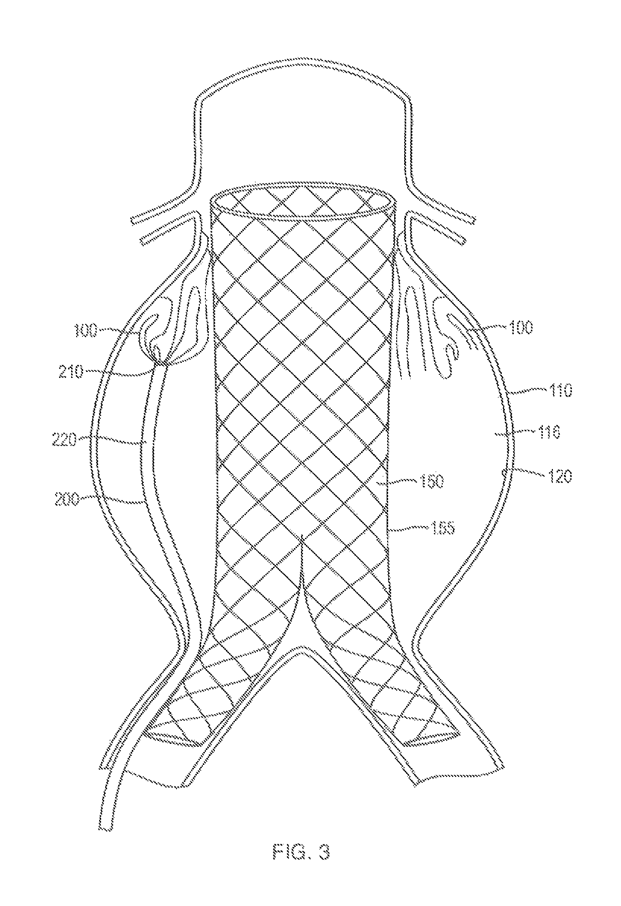
Such endoleaks represent a significant possible drawback to EVAR procedures as they could lead to aneurysm expansion or rupture.
Endoleaks are less of a concern following surgical repair of AAA, but the surgical procedure is significantly more invasive and has higher mortality and morbidity.
Such a pre-formed foam, however, cannot be shaped in-situ to conform to the configuration of the aneurysm sac.

Method used


Image

  • In-situ forming foams for treatment of aneurysms
  • In-situ forming foams for treatment of aneurysms
  • In-situ forming foams for treatment of aneurysms

Examples


example 1

[0105]An elastic silicone tube was used to simulate an aneurysm with two feeding vessels. This tube was placed over and sealed onto a rigid acrylic tube used to represent a stent-graft. The volume of the space between these two tubes was approximately 6 mL and was filled with water. A one-part polymer formulation was injected via syringe into this space, where it reacted and expanded in-situ to form a foam. This demonstrates that the foam can expand as desired into an anatomy analogous to an EVAR grafted aneurysm.

[0106]In this example, the foam was made from a polymer consisting of an isocyanate and a polyol. The formulation consisted of a mixture of the polymer, a diluent, a catalyst and a surfactant. In total, 1.4 mL of this mixture was injected to fill the space.

example 2

[0107]In this example, a one-part polymer formula was delivered through a 90 cm, 5 Fr catheter into a silicone aneurysm model that was connected to a flow system. The aneurysm model was similar in size to a human abdominal aortic aneurysm and an endovascular stent-graft was placed across the aneurysmal segment (AneuRx®, Medtronic CardioVascular, Santa Rosa, Calif.). Within the aneurysmal segment, three silicone tubes were attached to mimic the inferior mesenteric artery and two lumbar arteries. These tubes were in fluid communication with the aneurysm. Static pressure heads were placed on all three tubes to simulate arterial pressure. The silicone aneurysm model was filled with water and connected to a flow loop comprised of silicone tubing and a peristaltic pump set to a flow rate of 1.6 L / min, similar to human cardiac output. The flow loop was placed in a water bath at 37 C, maintained by an immersion circulator. The total volume of the aneurysm was 145 mL and the volume of the an...

example 3

[0109]A polymer hydrophobic, MDI-based quasi polymer was deployed into two sheep models of abdominal aortic aneurysm and an in-situ forming foam injected via syringe to fill the excluded aneurysm space. The polymer was mixed with a diluent, a catalyst and a surfactant to optimize deliverability and reaction kinetics.

[0110]In the first model, an aneurysm was created in the sheep model using an anterior patch. In this model, a Dacron patch (HEMASHIELD®, Boston Scientific Corp., Natick, Mass.) was surgically inserted into the abdominal aorta. Doing so created a pocket of additional volume along the aorta. The sheep used was a 108 kg sheep with an abdominal aorta inner diameter of 9.2 mm. A 5 Fr catheter was advanced into the newly created aneurysm sac by angiography. To simulate a stent-graft excluding the aneurysm sac, a second 0.035″ guidewire was inserted into the aorta to guide an 8 cm×10 mm DORADO® (CR Bard, Inc., Murray Hill, N.J.) balloon across the opening of the aneurysm sac. ...


PUM

PropertyMeasurementUnit
viscosityaaaaaaaaaa
viscosityaaaaaaaaaa
densitiesaaaaaaaaaa

Abstract

Systems, methods and kits relating to in-situ forming polymer foams for the treatment of aneurysms are disclosed. The systems include an insertable medical device and an in-situ forming foam that is formed from a polymer that reacts in an aqueous environment. When used to treat an aneurysm, the foam is placed into contact with at least a portion of an exterior surface of the medical device and / or the tissue surface of the aneurysm.

Description

CROSS-REFERENCE TO RELATED APPLICATIONS[0001]This application is a continuation-in-part of U.S. application Ser. No. 13 / 209,020 filed Aug. 12, 2011 and titled “In-situ Forming Hemostatic Foam Implants,” which is a continuation-in-part of U.S. application Ser. No. 12 / 862,362, filed Aug. 24, 2010 and titled “Systems and Methods Relating to Polymer Foams,” which claims priority to U.S. Provisional Patent Application Ser. No. 61 / 236,314 filed Aug. 24, 2009 and titled “Systems and Methods Relating to Polymer Foams,” each of which are incorporated by reference herein for all purposes. This application also claims priority to U.S. Provisional Patent Application Ser. No. 61 / 601,151 filed Feb. 21, 2012 and titled “In Situ Forming Implants to Treat Endoleaks,” which is incorporated by reference herein for all purposes.FIELD OF INVENTION[0002]Systems and methods relating to polymer foams for the treatment of aneurysms are generally described.BACKGROUND[0003]Early stabilization of body fluid lo...

Claims


Application Information

Patent Timeline
Patent Type & Authority Patents(United States)
IPC IPC(8): A61F2/82A61L31/18A61L31/06A61L31/14A61M25/00
CPCA61L31/14A61L31/146A61L31/141A61L31/18A61L31/06C08L75/04A61L2400/06A61M25/007A61L2430/36
Inventor SHARMAZUGATES, GREGORYBUSOLD, RANYFREYMAN, TOBY
Owner MEDTRONIC VASCULAR INC
Learn More