
Bearing ring

a bearing ring and bearing technology, applied in the direction of bearings, shafts and bearings, rotary bearings, etc., can solve the problems of affecting the reduction of bearing stiffness and strength, the measurement of strain, and the bearing ring only has small dimensions, so as to reduce the mechanical stiffness of the bearing ring and the effect of influencing the mechanical strength of the bearing

Active Publication Date: 2019-10-01
AB SKF
View PDF11 Cites 2 Cited by
  • Summary
  • Abstract
  • Description
  • Claims
  • Application Information

AI Technical Summary

Benefits of technology

The invention proposes a bearing ring that allows for a strong connection between the glass fiber core and the component without significantly decreasing the mechanical strength of the bearing ring. This allows for proper measurement of stresses while maintaining the mechanical stiffness of the bearing ring, resulting in a long life-time for the bearing ring.

Problems solved by technology

Specifically in the latter case problems arise because the glass fiber is normally equipped with a plurality of coaxially arranged cover layers.
Thus, specifically the measurement of strains is problematic due to the elasticity.
This is specifically a problem when the component is not even or flat but if it has a spherical shape.
Another problem is arising when the bearing ring has only small dimensions.
In this case machining grooves for embedding of the glass fiber in the bearing ring often takes away much steel and thus affects a significant reduction in the bearing stiffness and strength.
Small bearing rings with respective grooves may damage easily and therefore sustain short service life.
Also, a high temperature bonding of glass fibers for carrying out the fiber Bragg grating method is always challenging.
Traditional polymer glue does not meet with the requirements which have to be demanded for proper measurement of temperatures.
Finally, the installation and sustainability of bearings for installation and after installation is also often a problem.
There have been no pre-known designs which solve the mentioned problems.
Connections methods have been known for small bearings but the connection of the glass fiber to the bearing ring protects only from oil and grease rather than provide a robust integration and high temperature applications.

Method used


Image

  • Bearing ring
  • Bearing ring

Examples


Embodiment Construction

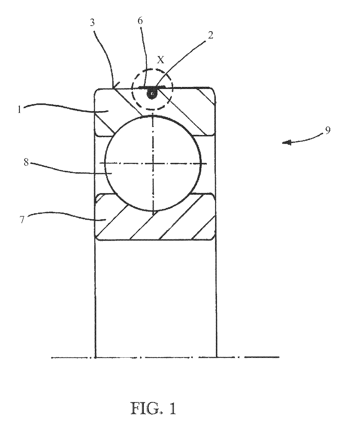
[0038]In the figures a roller bearing 9 being a deep groove ball bearing in the present embodiment (of course other kinds of bearings are also possible) is depicted which has an outer bearing ring 1, an inner bearing ring 7 and roller elements 8 which are arranged between the bearing rings 1 and 7.

[0039]In the outer bearing ring 1 and more specifically in its radial outer surface 3 a sensor element 2 is mounted. The sensor element 2 is a glass fiber and allows the measurement of strains in the bearing ring 1. The survey of those strains is carried out by the Fiber Bragg Grating (FBG) method or by the Chemical Composition Grating (CCG) method which are known as such. Reference is made e.g. to U.S. Pat. No. 6,923,048 B2 where this technology is explained in more detail.

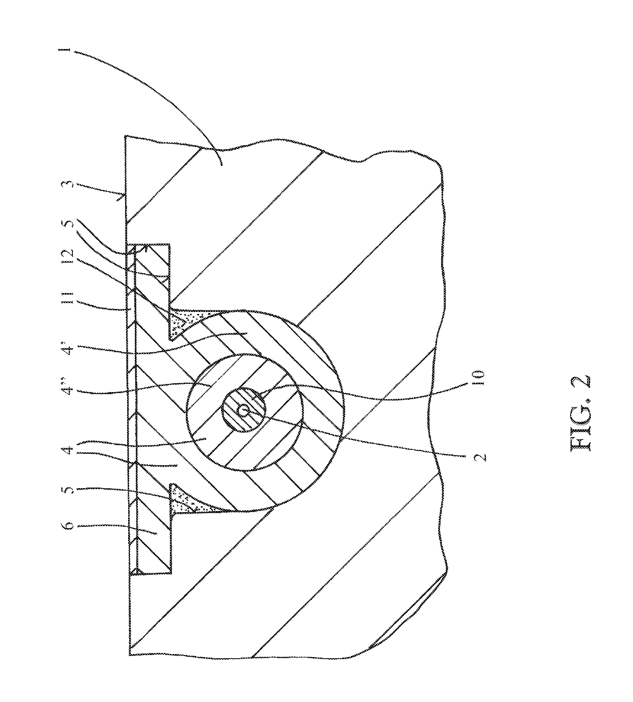
[0040]For the fixation of the glass fiber 2 in or at the bearing ring 1 a small groove 5 is machined into the outer surface 3 of the bearing ring 1 which runs around the whole circumference of the bearing ring 1. The se...


PUM


Abstract

A bearing ring having an elongated sensor element that runs along at least a part of a surface of the bearing ring. The connection between the sensor element and the bearing ring is established by a metallic metal material connected by material bonding with the bearing ring as well as with the sensor element. To improve the life of the bearing a sensor element is arranged in a groove that is machined in the bearing ring. The groove extends from the surface of the bearing ring. The metallic material includes or is connected with a flat metallic strip. The flat metallic strip is arranged at or in the surface of the bearing ring and covers the groove.

Description

CROSS REFERENCE[0001]This is a United States National Stage Application claiming the benefit of International Application Number PCT / EP2014 / 078664 filed on Dec. 19, 2014, of which is incorporated herein by reference in its entirety.FIELD OF THE INVENTION[0002]The invention relates to a bearing ring having an elongated sensor element that runs along at least a part of a surface of the bearing ring. More particularly, the invention relates to a connection between the sensor element and the bearing ring that is established by a metallic material.BACKGROUND OF THE INVENTION[0003]It is known to equip a bearing ring with a glass fiber element to allow the measurement of different physical parameters. By doing so, a survey of the parameters becomes possible by using the fiber Bragg grating (FBG) method. By this method temperatures as well as strains of the machine arrangement can be monitored.[0004]For doing so it is necessary to connect a glass fiber with the component. For surveying temp...

Claims


Application Information

Patent Timeline
Patent Type & Authority Patents(United States)
IPC IPC(8): F16C19/52F16C33/58F16C19/06
CPCF16C19/522F16C33/586F16C19/06
Inventor YANG, HONGYULANG, DEFENGSTORKEN, JOZEF MARIA
Owner AB SKF
Learn More