Supersonic separation of hydrocarbons

a technology of hydrocarbons and supersonic separation, which is applied in the direction of separation process, sustainable manufacturing/processing, gaseous mixture working up, etc., can solve the problems of increasing the probability, increasing the droplet volume, and enhancing the potential for collection

Active Publication Date: 2019-10-08
EASTMAN CHEM CO
View PDF16 Cites 1 Cited by
  • Summary
  • Abstract
  • Description
  • Claims
  • Application Information

AI Technical Summary

Benefits of technology

[0009]Supersonic separation methods operate by accelerating a gas mixture to supersonic speeds by passing the mixture through a converging-diverging nozzle. The expansion process lowers the temperature and pressure of the gas mixture. If the partial pressure of a condensable component in the vapor is decreased below the vapor pressure of that component at the local temperature, homogeneous nucleation can commence, initiating the formation of small droplets of the condensate that may then grow via condensation and coagulation mechanisms. These droplets are typically very small (of the order of 0.1 microns) and generally travel with the speed of the gas. To collect these droplets, supersonic separators utilize swirl vanes and other devices to induce centripetal acceleration of the droplets toward the nozzle walls, where they may be captured. The swirling devices also increase local turbulence levels within the separator, greatly increasing the probability of droplet-droplet collisions which lead to larger droplet volumes and enhanced potential for collection.
[0012]In embodiments directed to gas separation, a stream of gases or a mixture of gas and vapor passes through a de Laval nozzle, and accelerates to supersonic speed (c>Mach 1). As the gas leaves the nozzle at supersonic speed, both pressure and temperature fall. Gases derived from lower boiling materials condense as a liquid, and high-boiling gases are recovered as gases. The stream of gases is subjected to a vortex chamber or similar device, which causes vapors to swirl around a central axis as they leave the nozzle; centrifugal forces aid in separation of condensed gases from the gas or vapor stream.
[0023]In various embodiments, the C2 to C4 hydrocarbons comprise C2 to C4 unsaturated hydrocarbons, and are recovered from a waste gas stream from a hydroformylation reactor. If the waste gas stream is derived from a hydroformylation reactor, the waste gas stream may comprise C3 to C5 oxygenated compounds, particularly aldehydes, in addition to C2 to C4 hydrocarbon gases. In such a case, the method may further comprise a step of condensing the oxygenated compounds from said waste gas stream prior to passing the waste gas stream into the inlet of the de Laval nozzle so as to prevent contamination of the condensed hydrocarbon gases by the oxygenated compounds. Alternatively, a waste gas stream comprising C2 to C4 hydrocarbon gases and vapor-phase C3 to C5 oxygenated compounds may be treated by expansion in a de Laval nozzle to condense droplets comprising hydrocarbons and C3 to C5 oxygenated compounds. The resulting condensed mixture may be distilled to recover volatile hydrocarbons as an overhead stream.

Problems solved by technology

The swirling devices also increase local turbulence levels within the separator, greatly increasing the probability of droplet-droplet collisions which lead to larger droplet volumes and enhanced potential for collection.

Method used


Image

  • Supersonic separation of hydrocarbons
  • Supersonic separation of hydrocarbons
  • Supersonic separation of hydrocarbons

Examples


example1

Separation of Propane from a Propane / Air Mixture

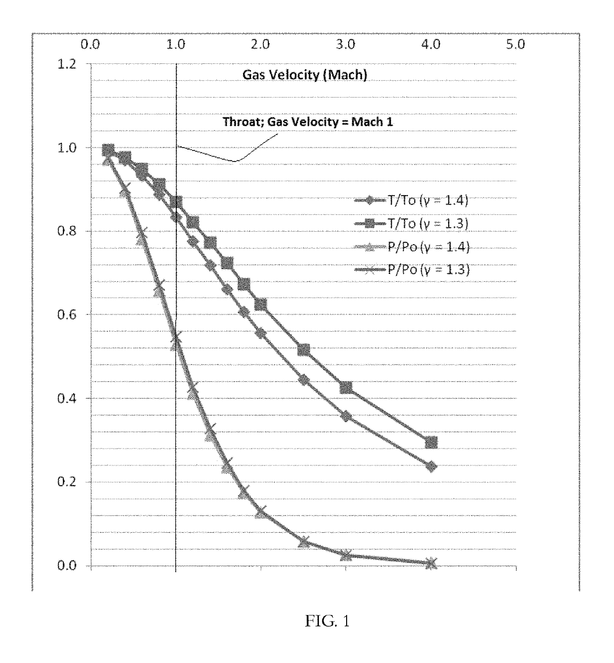
[0122]Separation of propane from a gas stream of mixture of air and propane gas may be accomplished using a de Laval nozzle, where the gas-stream is at an initial pressure of 21 bar, and an initial temperature of 313° K. The gas mixture contains 20 mol % propane at partial pressure P1 and 80 mol % air at partial pressure P2; by the relationship P=P1+P2, the mixture under these initial conditions contains air at a partial pressure of 16.8 bar and propane at a partial pressure of 4.2 bar. Since the mixture is predominantly air, γ is assumed to be ˜4.4.

[0123]FIG. 5A shows the equilibrium vapor pressure of propane (bar) as a function of temperature (degrees K). Table 2 shows the change in temperature and propane partial pressure as the gas accelerates from Mach 1, at the nozzle throat, to Mach 2.

[0124]

TABLE 2Propane Partial Pressure (Bar) in a de Laval Nozzle.PropanePropaneVelocityT (Air,P / PoPartialEquilibrium(Mach)degrees K)(γ = 1.4)Press...

example 2

Separation of Propane from a Propane / Ethane Mixture

[0128]Use of a de Laval nozzle also allows separation of propane from a mixture of ethane gas and propane gas at an initial pressure of 21 bar, and an initial temperature of 313° K. The gas mixture contains 20 mol % propane at partial pressure P1 and 80 mol % propane at partial pressure P2; by the relationship P=P1+P2, the mixture under these initial conditions contains ethane at a partial pressure of 16.8 bar and propane at a partial pressure of 4.2 bar. The term γ is assumed to be substantially constant at ˜1.3, as the mixture is a mixture of hydrocarbon gases.

[0129]FIG. 5A and FIG. 5B show the equilibrium vapor pressures of propane and ethane (bar), respectively, as a function of temperature (degrees K). Table 3 presents the change in temperature and partial pressures as the gas accelerates from Mach 1, at the nozzle throat, to Mach 3. At the nozzle throat (Gas velocity c=Mach 1), the partial pressures of ethane and propane in th...

example 3

Separation of C3 Hydrocarbons from a Hydroformylation Waste Gas Stream

[0131]A simulated process purge stream was examined in the supersonic separator model, where the stream contains the following gases, expressed in terms of mol % of the total: Hydrogen 43%, nitrogen 14%, carbon monoxide 13%, carbon dioxide 3%, methane 3%, ethane 0.5%, propane 21%, and propene 1.5%. Thus, about 86% of the hydrocarbon gases were C3 hydrocarbons (propane and propene). The process stream was simulated at 305 psig [21.03 bar (g)] and a flow rate of 40 thousand standard cubic feet per minute. Table 4 shows the C3 fraction recovery as a function of feed temperature. The C3 recovery is defined as mass fraction of C3s in liquid relative to the total C3s in feed. Each stage of C3 hydrocarbon separation from a supersonic gas stream was modeled in a bench-scale de Laval nozzle capable of a Mach 2 expansion.

[0132]

TABLE 4C3 Recovery from a Hydroformylation Waste StreamFeed TemperatureC3 Recovery(C.)(%)401720280...


PUM

PropertyMeasurementUnit
pressureaaaaaaaaaa
temperatureaaaaaaaaaa

Abstract

Selective recovery of C2 to C4 hydrocarbons is achieved through the use of a converging-diverging nozzle, or de Laval nozzle. The vapor stream comprising C2 to C4 hydrocarbons is fed into an inlet of a de Laval nozzle having a throat. The vapor stream may have an initial temperature of between 0° C. and 100° C., and an initial pressure of between 200 psig and 500 psig. In the de Laval nozzle, the vapor stream expands after passing through the throat of the de Laval nozzle, producing a vapor stream having reduced temperature and pressure. Then, C2 to C4 hydrocarbons condense from the reduced-temperature vapor stream as liquid droplets, which may be recovered. Fractionation of C2 to C4 hydrocarbons by means of a de Laval nozzle is possible; the technique allows selective recovery of a stream enriched in propene from a mixture of propane and propene.

Description

BACKGROUND[0001]1. Field of the Invention[0002]This disclosure relates generally to recovering and / or recycling reactive hydrocarbon gases by condensation.[0003]2. Description of Related Art[0004]A de Laval nozzle, or convergent-divergent nozzle, is a tube that is pinched in the middle, and has an axisymmetric hourglass shape. De Laval nozzles are used to accelerate pressurized gases at low speed to a higher speed, more particularly a supersonic speed in the axial direction, by converting the heat energy of the flow into kinetic energy. Because of this, the nozzle is used in steam turbines, rocket engine nozzles, and supersonic jet engines.[0005]Operation of a de Laval nozzle depends on changing properties in a gas as it accelerates from subsonic to supersonic speeds. The speed of a subsonic flow of gas will increase if the pipe carrying it narrows because the mass flow rate is constant. The gas flow through a de Laval nozzle is normally isentropic. At the “throat,” where the cross-...

Claims


Application Information

Patent Timeline
Patent Type & Authority Patents(United States)
IPC IPC(8): B01D5/00F25J3/02F25J3/00B01D53/24B01D3/06B01D53/00B01D3/14C10G70/00B01D53/22
CPCF25J3/0242B01D5/006B01D3/148F25J3/0209F25J3/0238B01D3/06F25J3/0233C10G70/00B01D53/002F25J3/0219B01D5/00B01D53/24B01D2256/24Y02P70/34Y02C20/20B01D2257/7025F25J2240/40B01D2256/16B01D2257/7022F25J2200/02B01D53/229C10G31/06C10G5/06C10G2300/1081C10G2300/1088C10G2300/1092C10G2400/20Y02P70/10
Inventor SHAIKH, ASHFAQ SHAHANAWAZPONDER, ANTHONYTOLLESON, GINETTE
Owner EASTMAN CHEM CO
Why Eureka
Try Eureka