Triboelectric generation device

a triboelectric generation and generating device technology, applied in the direction of influence generators, electrostatic generators/motors, non-conductive materials with dispersed conductive materials, etc., can solve the problems of increasing the amount of materials required for increasing the size limiting the output of the triboelectric generating device, so as to improve the output value of the triboelectri

Inactive Publication Date: 2019-11-05
SAMSUNG ELECTRONICS CO LTD +1
View PDF15 Cites 1 Cited by
  • Summary
  • Abstract
  • Description
  • Claims
  • Application Information

AI Technical Summary

Benefits of technology

[0010]The present disclosure may control surface charge density of materials of a triboelectric charging member to improve an output value of a triboelectric generating device, and therefore, embodiments of the triboelectric generating device of the present disclosure may achieve improved output with the same thickness and area. That is, a first charging layer includes a ferroelectric polymer matrix and ferroelectric inorganic particles dispersed in the ferroelectric polymer matrix. The ferroelectric polymer matrix exhibits interfacial polarization due to external pressure. The ferroelectric inorganic particles dispersed in the ferroelectric polymer matrix causes a local polarization effect through strain generated by interfacial friction and deformation, leading to an additional increase of a potential difference and resulting in improvement of the overall output of the triboelectric generating device. Embodiments of the triboelectric generating device of the present disclosure may be manufactured in the form of a flexible film, and embedded in a vibrating structure, a strap, a buckle, etc. to generate electricity by using friction generated by vibration or human motion.

Problems solved by technology

Therefore, in generating induction electricity from static electricity induced by friction, the existing triboelectric generating devices show a limitation in output due to electrification characteristics of existing triboelectric materials.
However, these techniques increase a size of the triboelectric generating device, and also increase amounts of materials required for the triboelectric generating device.

Method used


Image

  • Triboelectric generation device
  • Triboelectric generation device
  • Triboelectric generation device

Examples


example 1-10

Parts by Weight of Inorganic Particles (Based on 100 Parts by Weight of Polymer Matrix)

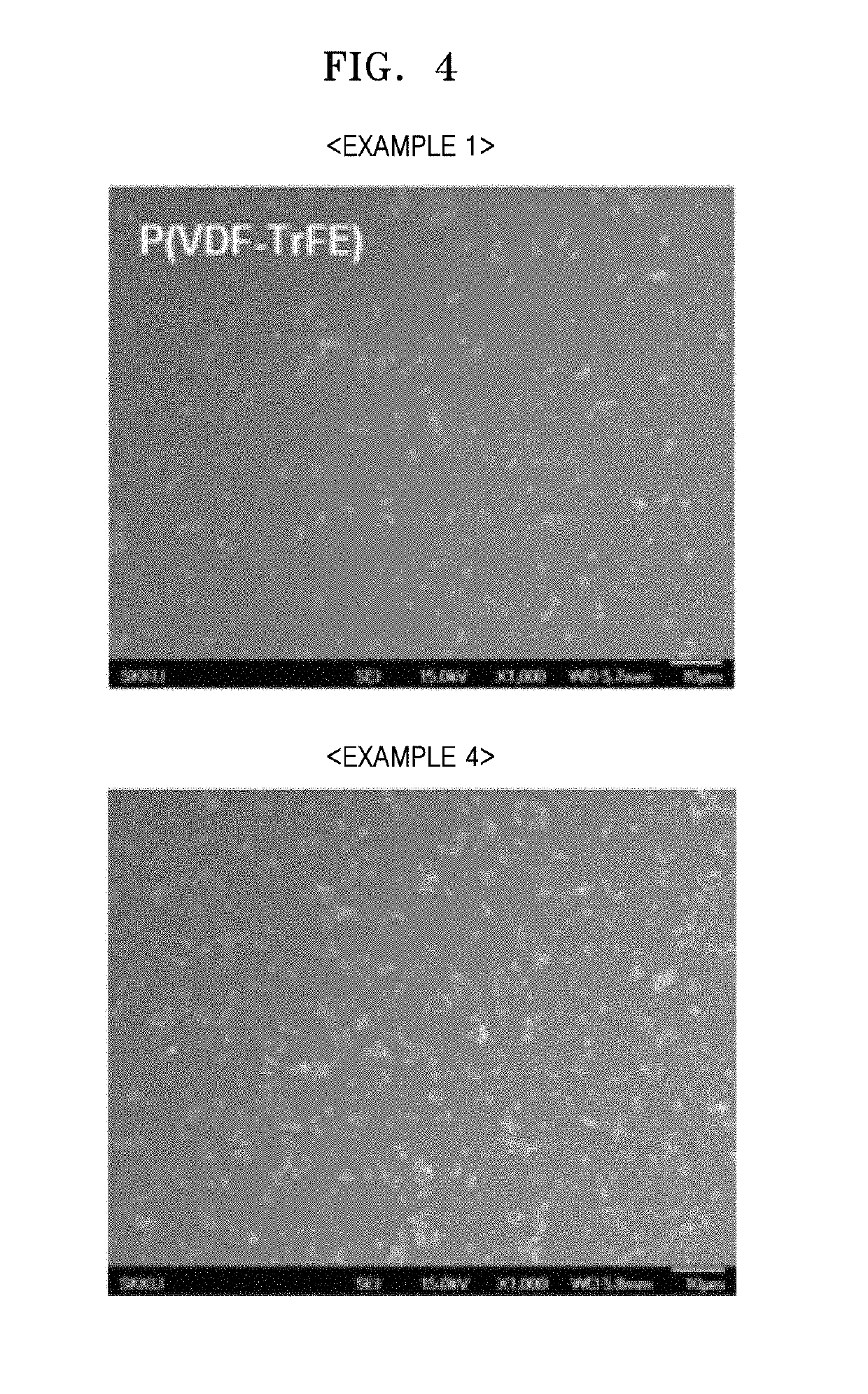
[0046]First, 0.8 g of P(VDF-TrFE) (France, PIEZOTECH, P(VDF-TrFE) copolymer powder 70 / 30% mol, 1.8 kg / m3), 0.08 g of barium titanate (BaTiO3) (USA, Sigma Aldrich, Barium titanate (IV), <3 μm), and DMF (dimethylformamide) (USA, Sigma Aldrich, N,N-Dimethylformamide) (use of solvent: 60 parts by weight, based on 100 parts by weight of a total of the inorganic particles and the polymer matrix) were mixed to prepare a dispersion solution for forming a first charging layer.

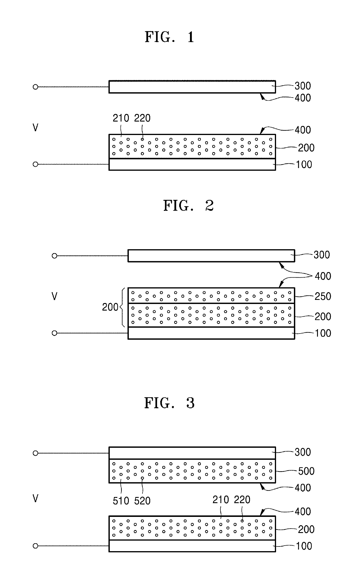
[0047]Next, the dispersion solution for forming a first charging layer was spin-coated onto a first electrode (ITO thin film having a thickness of 200 μm formed on a PEN (polyethylene naphthalate) substrate having a thickness of 200 μm), and then dried at 80° C. for 10 minutes to form a first charging layer having a thickness of 10 μm. A scanning electron microscopy image of a surface of the first charging layer thus formed is shown i...

example 2-5

Parts by Weight of Inorganic Particles (Based on 100 Parts by Weight of Polymer Matrix)

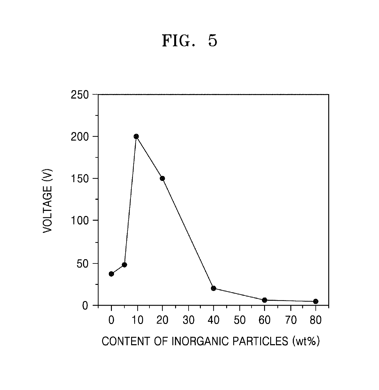
[0050]A triboelectric generating device of Example 2 was manufactured in the same manner as in Example 1, except that 0.04 g of barium titanate (BaTiO3) was used. Next, in the same manner as in Example 1, a potential difference between a first electrode and a second electrode was measured.

example 3-20

Parts by Weight of Inorganic Particles (Based on 100 Parts by Weight of Polymer Matrix)

[0051]A triboelectric generating device of Example 3 was manufactured in the same manner as in Example 1, except that 0.16 g of barium titanate (BaTiO3) was used. Next, in the same manner as in Example 1, a potential difference between a first electrode and a second electrode was measured.


PUM

PropertyMeasurementUnit
particle sizeaaaaaaaaaa
thicknessaaaaaaaaaa
particle sizeaaaaaaaaaa

Abstract

The present disclosure enables materials of a triboelectric charging member to exhibit a characteristic of increased surface charge density, thereby improving output of a triboelectric generating device. Accordingly, the present disclosure provides a triboelectric generating device showing improved output without increasing a size of the triboelectric generating device or without increasing amounts of materials required for the triboelectric generating device. An embodiment of a triboelectric generating device provided according to a first aspect of the present disclosure includes a first electrode; a first charging layer formed on the first electrode; and a second electrode disposed on the first charging layer, wherein the first charging layer and the second electrode are arranged such that an interface between the first charging layer and the second electrode forms a frictional interface, and the first charging layer includes a ferroelectric polymer matrix and ferroelectric inorganic particles dispersed in the ferroelectric polymer matrix.

Description

[0001]This application is the U.S. national phase of International Application No. PCT / KR2015 / 012847 filed Nov. 27, 2015 which designated the U.S. and claims priority to KR Patent Application No. 10-2014-0172379 filed Dec. 3, 2014, the entire contents of each of which are hereby incorporated by reference.TECHNICAL FIELD[0002]The present disclosure relates to an energy harvesting device by vibration (mechanical energy). More particularly, the present disclosure relates to a triboelectric generating device that generates electricity through friction.BACKGROUND ART[0003]A technology of generating triboelectricity is a technology of generating electricity from a potential difference induced by friction generated by external pressure or vibration at an interface between different dielectric materials or at an interface between a dielectric material and a metal. The technology of generating triboelectricity is known to provide an output that is about 10 times to about 100 times that provi...

Claims


Application Information

Patent Timeline
Patent Type & Authority Patents(United States)
IPC IPC(8): H02N1/04H01B1/20H02N1/08H02N1/00H02N1/10
CPCH02N1/04H01B1/20H02N1/08H02N1/10
Inventor PARK, YOUNG-JUNKIM, SANG-WOOPARK, YUN-KWONSEUNG, WAN CHULYOON, HONG-JOONLEE, KEUN YOUNGLEE, JEONG HWANLEE, JU-HYUCK
Owner SAMSUNG ELECTRONICS CO LTD
Why Eureka
Try Eureka