Unlock instant, AI-driven research and patent intelligence for your innovation.

Liquid cooled radial power plant having an external coolant manifold

a technology of radial power plants and coolant manifolds, which is applied in the direction of machines/engines, mechanical energy handling, mechanical apparatus, etc., can solve the problems of insufficient cooling of head materials, inability to perform lubricating functions, and configuration as in-line blocks

Active Publication Date: 2019-11-19
UNIGEN POWER INC
View PDF21 Cites 3 Cited by
  • Summary
  • Abstract
  • Description
  • Claims
  • Application Information

AI Technical Summary

Benefits of technology

The present invention relates to various systems and methods for ground-based, water (fluid) cooled radial engines used for power generation, as well as cooling systems for these engines using liquid cooling. The invention also includes designs for radial engines that use multiple cylinder extensions with fluid conduits for porting coolant, as well as a design that includes a flange for securely attachment of the engine's sleeve to the outside of the hub. The technical effects of the invention include improved cooling efficiency, higher peak power output, and increased durability and reliability of the ground-based, water cooled radial engines, making them suitable for use in portable electric power generators.

Problems solved by technology

Indeed, with lighter weight aluminum heads (as opposed to heavier cast iron), the head material could melt without adequate cooling.
In addition, excessive temperatures can break down oil, so that it does not perform its lubricating function.
In limited applications, such as the P-51 Mustang by Allison-Packard and certain Rolls Royce V-12 aircraft engines, water cooling was employed where a radial configuration was deemed to compromise aerodynamics.
But those engines were configured as in-line blocks, which are not suitable for air cooling in the way radial engines are.
However, all presently known known water cooled radial engines have been limited to aircraft (non-ground based) flight applications.
The Kealy radial engine configuration employs air cooling, but is limited in its ability to reject heat in a ground based system at high ambient temperatures, especially at the exhaust valve ports.
In addition, the large fan (e.g., 60 inches in diameter) required to move the cooling air (e.g., 22,000 cubic feet per minute (CFM)) created high ambient noise, which can be problematic in urban areas which may impose noise restrictions.

Method used


Image

  • Liquid cooled radial power plant having an external coolant manifold
  • Liquid cooled radial power plant having an external coolant manifold
  • Liquid cooled radial power plant having an external coolant manifold

Examples


Embodiment Construction

[0028]The following detailed description of the invention is merely exemplary in nature and is not intended to limit the invention or the application and uses of the invention. Furthermore, there is no intention to be bound by any theory presented in the preceding background or the following detailed description.

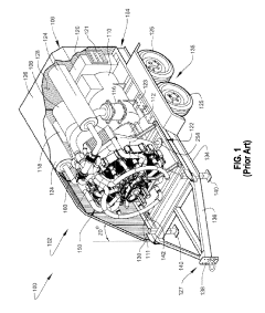
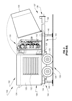
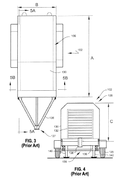
[0029]Various embodiments of the present invention relate to a water cooled radial engine for ground based use, for example, to drive an electric power generator.

[0030]The primary function of an engine block is to support the crankshaft, and to provide a path for the piston to reciprocate and the connecting rods to connect the pistons to the crank shaft. In an in-line engine, the block also contains the channels or conduits for supplying coolant to and from the area water jackets surrounding the cylinder bore and / or cylinder head (sometimes referred to as water jackets). That is, the coolant paths which bring fluid into and out of the cooling jackets are integral to the engi...


PUM


Abstract

Methods and systems for cooling a radial engine in a ground-based portable electric power generating system. The engine includes a plurality of cylinders extending radially from a central hub supporting a crankshaft. Each cylinder has a coolant inlet port and a coolant outlet port. The cooling system includes an inlet coolant manifold interconnecting at least two of the coolant inlet ports. The inlet coolant manifold is disposed external to the central hub.

Description

TECHNICAL FIELD[0001]The present invention relates, generally, to a fluid cooled radial engine for use in a ground-based electric power generator system and, more particularly, to a coolant system for a radial engine having a coolant manifold which is external to the engine housing.BACKGROUND[0002]The high combustion temperature of an internal combustion engine requires the heat to be removed to prevent damage to the pistons and cylinders. Indeed, with lighter weight aluminum heads (as opposed to heavier cast iron), the head material could melt without adequate cooling. In addition, excessive temperatures can break down oil, so that it does not perform its lubricating function. It is thus imperative to reject heat from an internal combustion engine, either through air cooling or fluid cooling (typically water combined with a chemical coolant additive).[0003]Aircraft engines typically employ air cooling rather than water cooling due to the abundance of ram air and the extra weight oc...

Claims


Application Information

Patent Timeline
Patent Type & Authority Patents(United States)
IPC IPC(8): F02P3/02F02B63/04F01B1/06F02B75/22F01P3/02H02K7/18F01P11/04F02F1/10F02F1/16H02K19/16H02K9/19H02K5/24
CPCF02B63/048F02F1/10F01P11/04F01B1/062H02K7/1815F01P3/02F02B75/222F02F1/102H02K19/16F02F1/166H02K9/19F01P2003/021H02K5/24H02K5/203
Inventor CARMEN, JR., ANTHONY JOSEPHSALVATORE, NICHOLAS ANTHONY
Owner UNIGEN POWER INC