Method of moulding a composite article and mould

a composite article and moulding technology, applied in the field of moulding a composite article and a mould, can solve the problems of large production volume, difficult to precisely define the opposite surface produced by the surface of the vacuum bag, and the relatively short cycle time, so as to reduce the surface and improve the quality of the surfa

Active Publication Date: 2019-11-26
BLADE DYNAMICS LTD
View PDF13 Cites 0 Cited by
  • Summary
  • Abstract
  • Description
  • Claims
  • Application Information

AI Technical Summary

Benefits of technology

[0006]The presence of the grooves means that the flow resistance across the mould cavity from the point of injection is greatly reduced. Typically, the pressure difference between the inside and outside of the mould is less than 1 bar (100 kPa). This allows the equipment to be operated at a much reduced pressure. In fact, it is possible to rely on the suction pump alone thereby eliminating, or at least greatly simplifying, the use of costly pressure pumps and systems traditionally used in the prior art. It also allows the use of smaller mould parts with an associated cost saving and ease of handling.
[0007]The reduction in flow resistance means that more complex continuous fibre material can be used and it also allows a significant increase in the Fibre Volume Fraction (FVF). This is the proportion of the composite material by volume which is occupied by fibre rather than matrix material. The invention can even operate with 100% woven materials to produce structural components with high FVF.
[0008]The use of two rigid mould parts also provides superior dimensional accuracy, and stable and repeatable cured ply thickness can be achieved.
[0009]The improved surface also leads to a very low scrap rate, the part emerging from the mould requiring minimal trimming and rework.
[0010]Further, the consumable parts of the process are greatly reduced as the rigid mould parts can be reused unlike in the prior art process where the vacuum bag, distribution mesh and sealing tape are all consumable components. Initial estimates put the reduction of consumables at about 85%.
[0011]The above method can produce an article with two high quality surfaces each formed by a rigid mould part. At least one of these surfaces will have an arrangement of ribs corresponding to the arrangement of grooves. This may be acceptable for certain components, for example if the ribs are on an internal face of the article. If, however, an article without ribs is required, the method further includes the steps of placing a peel-ply layer between the fibres and the grooves on the adjacent surface of the mould; and, after removing the article, peeling the peel-ply layer to remove a layer of resin formed in the grooves from the remainder of the moulded article. With such an arrangement, all of the above-mentioned advantages concerning the accuracy of the moulding with two rigid mould parts and retained. There is a slight decrease in the surface quality of the surface formed after the peel-ply layer has been removed. However, even with the peel-ply layer, the method is far more controllable and repeatable than using a flexible mould surface.

Problems solved by technology

This process can produce large, complicated shapes and relatively short cycle times. However, this remains a relatively expensive process as the cost of the equipment to inject the resin under high pressure is high as is the cost of the tooling which can safely contain such pressure.
However, the opposite surface which is produced by the surface of the vacuum bag cannot be precisely defined given the distortions of the vacuum bag particularly in the vicinity of any well-defined corners.
This process also requires a relatively large number of consumable parts including the vacuum bag, the distribution mesh and the sealant tape required to seal the edge of the vacuum bag.

Method used


Image

  • Method of moulding a composite article and mould
  • Method of moulding a composite article and mould

Examples


Embodiment Construction

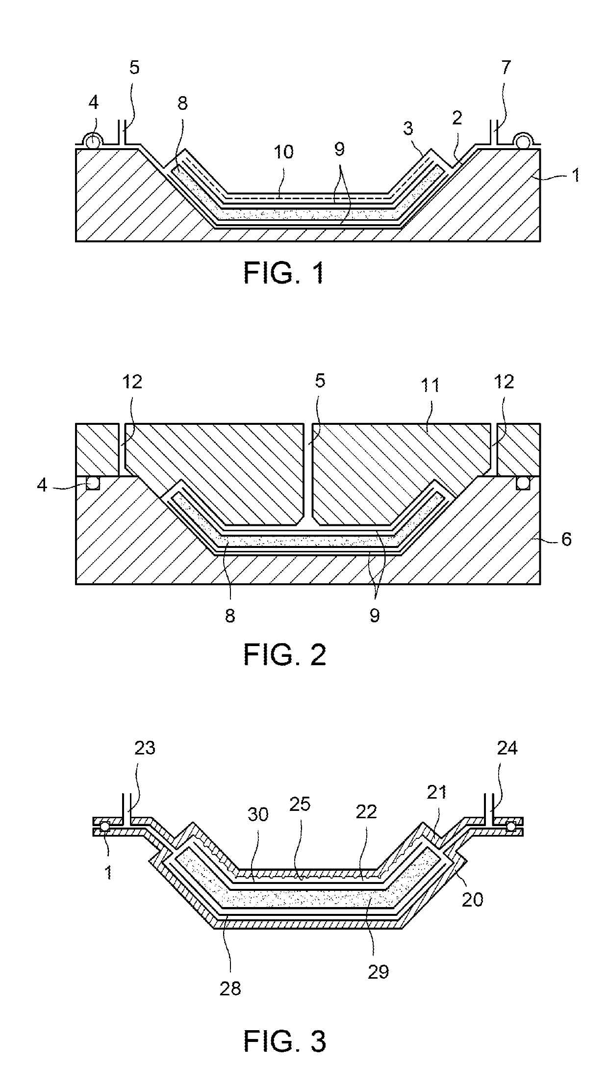
[0021]FIG. 1 is a schematic depiction of a vacuum assisted resin transfer moulding (VARTM) process. There is a single rigid mould tool 1 which has a first surface 2 forming a high quality mould surface.

[0022]The opposite side of the mould is created by a vacuum bag 3 which is a flexible membrane that is drawn into the required position by application of a vacuum. Thus, the mould cavity is created between the mould surface 2 and the vacuum bag 3. The mould cavity is sealed by a seal 4 between the vacuum bag 3 and mould tool 1. Resin is supplied along a resin inlet 5 by a high pressure pump. A vacuum pump provides suction at vacuum outlet 7 to draw resin across from the opposite side of the mould cavity.

[0023]In use, fibres 8 and peel-ply layer 9 are first laid up in the mould. A distribution media layer 10 is then placed on the stack to aid the flow of resin. The vacuum bag 3 is put in place and a vacuum is applied. Resin is then drawn through the mould cavity by the vacuum pump to w...


PUM

PropertyMeasurementUnit
pressure dropaaaaaaaaaa
angleaaaaaaaaaa
angleaaaaaaaaaa

Abstract

The present invention relates to a method of moulding a composite article using a mould. The mould includes first and second rigid mould parts between them defining a mould cavity. A reservoir of resin is connected to an inlet into the mould cavity. A suction pump is connected to a port on the opposite side of the mould cavity from the inlet. At least one of the mould parts has an arrangement of grooves on the surface facing the mould cavity to distribute resin across the mould cavity. The method includes laying up fibres in the mould cavity, injecting resin from the reservoir by running the suction pump to fill the mould cavity with resin, curing the resin article to form a moulded article and opening the mould and removing the article.

Description

BACKGROUND[0001]The present invention relates to a method of moulding a composite article and mould.[0002]There are a variety of composite manufacturing processes which each have advantages and disadvantages. The factors which drive selection of the process include structural quality of the part, cost, surface finish, production rate, volume and limitations of the method. Common composite manufacturing methods are hand lay-up, pre-preg lay-up, bag moulding, autoclave processing, compression moulding, resin transfer moulding, pultrusion and filament winding. The two methods that are most appropriate for comparison to the invention are both resin transfer moulding (RTM) processes. The two methods are conventional RTM and vacuum assisted RTM (VARTM).[0003]Resin transfer moulding (RTM) involves using a closed mould with two rigid surfaces. Fibre reinforcement is placed in the mould which is then closed. Liquid resin is then injected into the mould to wet out the reinforcement and fill t...

Claims


Application Information

Patent Timeline
Patent Type & Authority Patents(United States)
IPC IPC(8): B29C70/54B29C70/48B29C70/44B29C33/42
CPCB29C70/48B29C70/548B29C70/446B29C2033/422B29C70/54
Inventor BROOME, PETER ANTHONYHAYDEN, PAUL TREVOR
Owner BLADE DYNAMICS LTD
Why Eureka
Try Eureka